

The C-IT-0504L module, in its DIN rail version, offers the same features as the miniature C-IT-0504S module. It comes in a low-profile DIN rail enclosure (2M wide) with a connector featuring screw terminals.
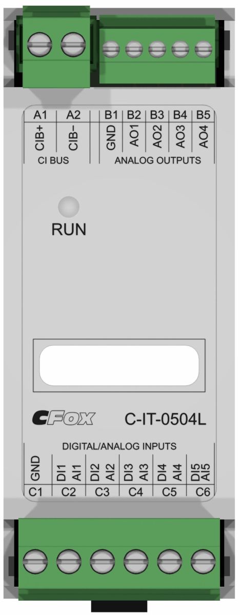
The C-IT-0504L module (order no.: TXN 143 26) is designed for connecting analog or binary signals and 0–10 V analog outputs directly to the CIB electrical installation bus.
The universal inputs can be configured as binary or analog in the module’s software, organized into two groups. The first group contains 4 inputs, and the second contains 1 input. The configuration is then applied uniformly to the entire group. For example, one temperature sensor (AI) and four contact inputs (DI), or one contact input (DI) and four temperature sensors (AI).
For temperature measurement, PT1000 and Ni1000 thermal resistors, an NTC12k thermistor, or a KTY81-121 thermistor are used in relation to the common GND wire. The resistance is converted by the module into a numerical temperature value and transmitted to the central unit via the CIB bus. For other types of resistance sensors, a resistance measurement range of 0 to 160 kΩ can be selected, but the conversion to temperature and linearization must be performed at the user program level.
Binary signals are connected to the inputs only as an open, voltage-free contact relative to the common GND conductor. The binary input can also operate in balanced input mode.
The voltage of the 0–10 V analog outputs is connected to the terminals relative to the common GND conductor.
General parameters for inputs DI/AI1 through DI/AI5
| Type of input (connected sensor) | measuring range |
| PT1000 | -90 °C - +320 °C |
| Ni1000 | -60 °C - +200 °C |
| NTC 12k | -40 °C - +125 °C |
| KTY81-121 | -55 °C - +125 °C |
| Maximum resistance | 0 ÷ 160 kΩ |
| Binary input | Log. 0 >1,5 kΩ / log 1 <0,5 kΩ |
| balanced input | resistor loop 2x 1k1 |
General parameters for analog outputs AO1 through AO4
| Rated Output Voltage (Vo) | 10 V |
| Adjustable output voltage range | 0 ÷ 130 % Vo |
| Load resistance | >1 kΩ |
| Max. load capacity | 250 nF |

Fig. 1: Example of the C-IT-0504L module wiring
The internal wiring of the module is identical to that of the C-IT-0504S, where you can find the wiring diagram.

Fig. 2: Connector layout on the C-IT-0504L module