
C-IS-0404S is a module in a miniature built-in design with 4x DO and 4x AI / DI. It is connected to the master system via the CIB bus. It contains four binary outputs that can be used (in pairs DO1 with DO2 and DO3 with DO4) as 'H bridges' or as PWM outputs of the open collector type for eg control of model actuators (only with external power supply), or as common transistor outputs 24 VDC 50 mA. It contains four universal inputs configurable in pairs (DI / AI1 with DI / AI2 and DI / AI3 with DI / AI4) either as binary allowing connection of a potential-free contact against a common GND conductor or as analog for direct connection of passive resistance sensors Pt1000, Ni1000, NTC 12k , KTY 81-121 (measured resistance value is converted in the module directly to a numerical temperature value), or general resistance measurement in the range 0–100 kΩ or DC voltage in the range 0–2 V.
The TXN 143 14 module is in a shrink tube and is equipped with terminal blocks with tongue terminals. The TXN 143 14.01 module is not protected by a tube or does not contain terminal blocks, all signals are routed to the socket strips, a built-in connection is assumed here by sliding the module onto the plugs of the expansion board.
|
Input parameters |
||
|
Input pair type (optional SW configuration) |
binary, Pt1000, Ni1000, NTC 12k, KTY 81-121, R=0–100 kΩ, U=0–2 V DC |
|
|
Galvanic separation of inputs from CIB |
no |
|
|
DI: binary input for potential-free contact |
0 while R>1,5 kΩ |
|
|
AI: sensor Pt1000 |
–90 °C ÷ +320 °C |
|
|
AI: sensor Ni1000 |
–60 °C ÷ +200 °C |
|
|
AI: sensor NTC 12k |
–40 °C ÷ +125 °C |
|
|
AI: sensor KTY 81-121 |
–55 °C ÷ +125 °C |
|
|
AI: resistive input |
0–100 kΩ |
|
|
AI: voltage input |
0–2 V DC |
|
|
Basic measurement accuracy |
0,5 % |
|
|
Output parameters, type 'half-H bridge' |
||
|
Power supply for UOUT output circuits |
22/12 V DC optional jumper |
|
|
Maximum current of all outputs |
40 mA |
|
|
Minimum output voltage UDOmin |
17 V while UOUT–>22 V |
|
|
Output parameters, PWM type |
||
| Servomotor power supply |
from external power supply |
|
|
Maximum supply voltage of the servomotor |
20 V DC1) |
|
|
Maximum current through DOx output |
100 mA |
|
|
PWM signal frequency |
50 Hz |
|
|
PWM signal shift setting range |
0–100 % |
|
|
Power output for position sensor |
||
|
Output voltage |
5±0,5 V DC |
|
|
Maximum output current |
30 mA |
|
|
Internal security |
yes (returnable fuse) |
|
1) The UOUT jumper must be set to the 22 V position
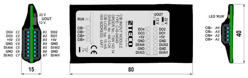
Fig. 1 Dimensions, terminal designations, signal placement on the terminal blocks, location of the output power jumper and the 'RUN' LED on the TXN 143 module 14
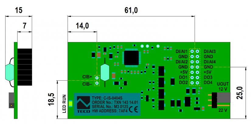
Fig. 2 Dimensions, location of signals on hollow rails, including their location on the board (the rails are from below), location of the output power jumper and LED 'RUN' on the TXN 143 module 14.01. PCB size: 78 × 37 mm.
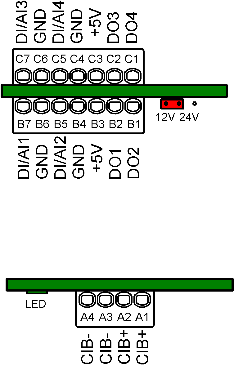
Fig. 3 Detailed connection of module terminals