
An example of connection of card readers SSA-R1000/R1100 (Samsung Format, 125 kHz) and SSA-R1001/R1101 (MIFARE, 13.56 MHz), produced by SAMSUNG, to the C-WG-0503S module is described in this chapter.
The C-WG-0503S module provides communication of Wiegand with the sensor and control of LEDs and the buzzer. Due to a high consumption, the sensor power supply must be provided by an external 12 VDC source (the 12 VDC output of the C-WG-0503S module cannot be used in this case).
Detailed technical information on the sensor can be found at the end of this chapter.
Fig. 1. An example of connecting the SSA-R1000/R1001 sensor to the C-WG-0503S module
Notes:
-
The cable for connecting the sensor can be as long as dozens of meters (the Wiegand interface allows the length of up to 150 m); the communication and control require a shielded cable with the minimum cross section of 0.35 mm2, the power supply only requires an unshielded cable with the minimum cross section of 0.75 mm2.
-
The consumption of the SSA-R1000 sensor from the supply voltage is specified at 120 mA, which does not meet the specifications of the C-WG-0503S module (a maximum consumption from the 12 V output is 60 mA), so the sensor must be powered from an external source.
-
The free inputs AI/DI4 and AI/DI5 can be utilized e.g. for connecting the temperature sensors (measuring the temperature in the room, etc.).
The properties and parameters of the SSA-R1000/R1100 and SSA-R1001/R1101 sensors
The SSA-R1000/1001/R1100/R1101 sensor is designed for contact-free reading (RFID) identifiers according to the type of Samsung 125 kHz Format (SSA-R1000 SSA-R1100) or MIFARE (SSA-1001, SSA-R1101) technology used. The sensor is equipped with red and green LED indicators and a buzzer.
The sensor is designated both for indoor and outdoor use, it is equipped with a compact housing and the interior electronics is embedded for maximum durability.
The sensor is mounted on the wall with two screws (approx. M3, or 3.5 mm wood screws), vertically above one another with the spacing of 8.38 cm; in the middle between the mounting holes there is a fixed connecting cable.
The cable is terminated with free coloured wires moulded (see tab. 2.) in a connector.
Tab. 1. The basic parameters of the SSA-R1000/R1100 and SSA-R1001/R1101 sensors
|
Technical parameters |
SSA-R1000 |
SSA-R1100 |
SSA-R1001 |
SSA-R1101 |
|
Nominal supply voltage |
12 VDC |
|||
|
Maximum current consumption |
120 mA 1) |
80 mA 1) |
||
|
Interface |
26 bits Wiegand |
34 bits Wiegand |
||
|
Reading distance – ISO card |
max. 10 cm 2) |
max. 10 cm 2) |
||
|
The RFID frequency range |
125 kHz |
13.56 Mhz |
||
|
The supported types of identifiers |
PSK 125 kHz, Samsung Format |
ISO 14443A Mifare 3) |
||
|
The type of sensor |
just for reading (read only) |
|||
|
Acoustic signal |
buzzer |
|||
|
Optical indication |
LED (green, red) |
|||
|
Terminating signals |
Cable, the length about 40 cm, the diameter of the insulation is 6mm |
|||
|
The cable termination |
Connector |
|||
|
Dimensions of the housing (width x height x depth) [mm] |
47 x 122 x 26 |
75.3 x 109 x 31 |
47 x 122 x 26 |
75.3 x 109 x 31 |
|
The range of operating temperatures |
-30 to +50 °C |
|||
|
Housing – colour, material |
Silver with a black stripe, polycarbonate |
|||
|
Protection |
IP 65 |
|||
-
The current consumption exceeds the 12 V output of the C-WG-0503S module, so the sensor must be powered from an external source (e.g. from the 12 V output level of the PS2-60/27 power supply, or from the DR-15-12 supply).
-
The distance is only valid for cards and identifiers supplied by the sensor manufacturer.
-
Only for reading of a unique serial card number.
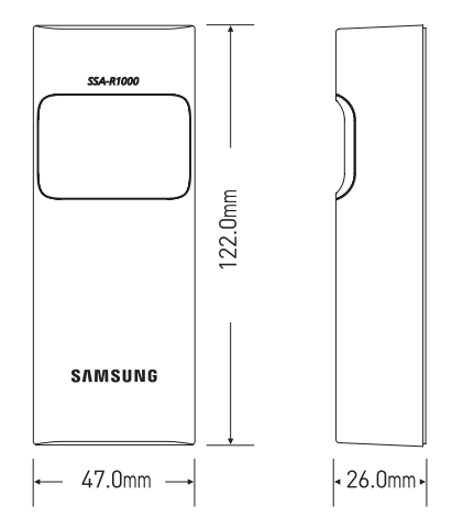
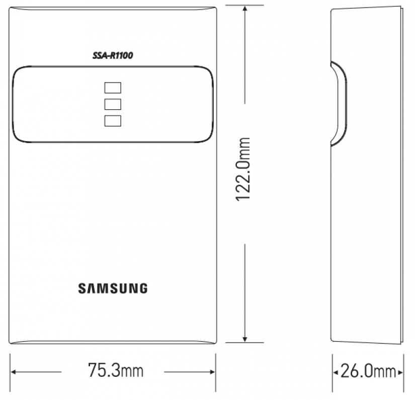
Fig. 2. The dimensions of the SSA-R100x and SSA-R110x sensors
Tab. 2. A description of the terminals and signals of the SSA-R1000/R1100 and SSA-R1001/R1101 sensors connectors
|
Connector PIN |
The colour of the wire |
Function |
Description |
|
1 |
yellow |
GLED |
green LED (it is activated by connecting the signal to GND) |
|
2 |
blue |
BEEP |
buzzer (it is activated by connecting the signal to GND) |
|
3 |
orange |
NC |
not used |
|
4 |
White |
data1 |
data wire, Data 1 Wiegand interface |
|
5 |
green |
data0 |
data wire, Data 0 Wiegand interface |
|
6 |
brown |
RS232(RX) |
RS-232 (not used) |
|
7 |
red |
+12V |
positive pole of the supply voltage |
|
8 |
black |
GND |
the ground of the supply voltage |
|
9 |
violet |
RS232(TX) |
RS232 (not used) |
|
10 |
grey |
SEL |
34/26 bit Wiegand selection (26 bit – by connecting to GND) |