
There are a number of devices available for monitoring of the opening of doors, which differ primarily in their mechanical design and the purpose. Some recommended types are described below.
When installing the detectors (magnetic contacts), you must follow a few guidelines:
-
The protected windows and doors must have an exacttly defined position when they are closed (e.g. their position must not be changed by wind, which could to a disconnection of the contact and a false alarm).
-
A maximum stated gap (for the switched - idle state) is considered in ideal conditions; any metallic ferromagnetic material in the vicinity of the contact reduces the range (e.g. metal door frames decrease the maximum gap by more than half).
-
The contact must be set as exactly as possible to achieve the best possible functionality.
-
The part of the contact with the terminal is always installed on the fixed part of the windows or doors (the frame).
-
The connection of a 2-wire or a 4-wire contact is illustrated in the following example.
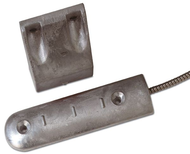
Monitoring of the opening of e.g. massive garage gate is provided by the MM-106 gate contact manufactured by ARITECH. It is a massive aluminium contact with a 30cm long terminated armoured cable.
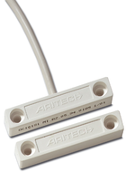
The DC-101 contact manufactured by ARITECH is suitable for monitoring standard windows and doors; the housing is white or brown, tho contact is surface mounted with two screws.
The TAP-10 contact is designed for flush mounting; it is available in white (the WH version) or brown (the BR version) plastic housing, and it should be flush-mounted into a bored hole.
Table.1: The Basic parameters of opening detectors
|
Type |
MM-106 |
DC-101 (DC-101-B) |
TAP-10 |
|
Maximum gap |
50 mm |
15 mm |
25 mm |
|
Mounting |
2 screws |
2 screws |
the hole with an 11mm diameter |
|
Connection |
A cable with 4 wires , 30 cm, armoured |
A cable with 4 wires, |
2 separate wires, 40 cm long |
|
Contact |
NC |
NC |
NC |
|
The contact operating voltage |
1 ÷ 50 VDC |
Max. 100 V/0.5 A |
|
|
Colour |
aluminium |
White (brown) |
white (WH), brown (BR) |
|
Dimensions |
175 x 50 x 15 mm |
50 x 9 x 9 mm |
11 x 32 mm |
|
A picture of the contact |
 |
 |
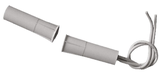 |
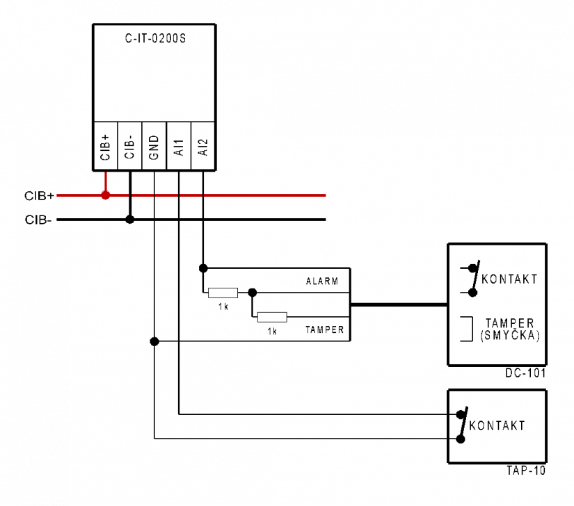
Fig. 1. An example of connecting 2 and 4-wire contacts to the C-IT-0200S module
Notes:
-
The example shows the wiring of the contact and the tamper loops in the DC-101 as double-balanced; the contact wires and the tamper loop wires in the cable must be connected correctly with the 1 k resistors (see the general description of double ballancing in Chap.8.1.1).
-
The lower magnetic contact represents a simple connection of an NC contact to the C-IT-0200S module.
-
Correct installation of the detector is specified in the product operating instructions.
-
A cable with the wire diameter of at least 0.3 mm can be used for the connection, e.g. the SYKFY cable; its length can be up to dozens of meters.