
When designing the dimming of power chips or current-actuated power LED strips (they are being used more thanks to their higher efficiency, compared with voltage LED strips), it is necessary to correctly dimension the power supply for the LEDs.
The requirements for the LED power supply
The C-DM-0006M-ILED dimmer enables powering from the 4.5 ÷ 48 VDC power supply, with a maximum current consumption of 4.2 A. It is advisable to select a slightly higher nominal voltage of the power supply (e.g. by 5 V) than the sum of maximum voltages in the chips of each channel connected in series. It is also recommended to have similar numbers of LEDs wired in series in each channel of the dimmer (e.g. if there is one chip connected to the LED1 output and 5 chips connected to the LED2 output with a voltage drop about 3.5V/chip, the dimmer must be powered by about 24 VDC power supply, which means that in the case of LED1 there will be a very high power dissipation in the module (as this channel only needs about 8 V power supply).
The following description presents an example of connection of specific LED chips on the C-DM-0006M-ILED module, which is powered by the DR-60-12 power supply.
The LED chip used: CREE XT-E R4/6300K, max. UF = 3,4 V, IF = 1,5 A, 231 lm/700 mA
The source used: DR-60-12
Cable: the wire cross-section is 0.5 mm2, the length is about 5 ÷ 15 m
The dimming module: C-DM-0006M-ILED
LED chips
The dimmed LED chips in the example are the CREE XT-E, soldered to aluminum PCB TR20-1M (manufactured by TRON); there are always two PCBs mounted on one cooler and located in the ceiling.
The XT-E chip comes in many variants, according to the desired colours of light; max. chip power consumption is 5 W, when excited by current of 1.5 A, the selected type reaches the luminous flux of 401 lm. When excited by 700 mA current, the luminous flux reaches 231 lm (it is clear that with the increasing current, the efficiency of the chips decreases).
Selecting a suitable power supply
If wiring 2 chips in series, you can count with a 2 x 3.4 V maximum voltage for power supply; we used a 12 V supply to have a sufficient margin. With the maximum current in all channels, the module takes from the supply 4.2 A, which requires at least a 50 W supply. In this case, it is beneficial to use the DR-60-12 power supply.
Switching the LED power supply (DR-60-12)
n order to prevent the power supply DR-60-12 from being constantly connected to the network and needlessly consume current, its input is switched by a 230VAC relay output; in this case the DO1 input of the C-IR-0203M module is used.
The inrush current (so-called “cold start”) of the power supply DR-60-12 stated by the manufacturer is up to 36 A, so it should be switched (just like a vast majority of similar power supplies for LEDs) by a relay with an appropriate contact, most often with the so-called “inrush technology”. The C-IR-0203M module is equipped with a relay with an inrush current of up to 80A. Therefore it is suitable for this purpose.
The measured results
In this connection, the maximum measured consumption of one chip was typically 2.2 W.
Before a test, 10 chips were placed in a suspended ceiling in a room, i.e. 5 pieces of coolers and each with two LEDs, with total power of 22 W; next to them were placed two 60 W incandescent bulbs, in total a 120 W, in all cases just the sources with no covers.
Then, illuminance was measured at floor level, always in the place with the highest intensity.
The illuminance at floor level by 120 W incandescent bulbs was in total 69 lx.
The illuminance at floor level by 22 W LED chips was in total 132 lx.
In this case, the approximate efficiency of LED illumination was about 10 times higher than that of incandescent lamps. What contributes to the positive result of LEDs is their lighting characteristics aiming directly down and the angle exceeding 120°, compared with omni-directional bulbs.
The following diagram shows another measurement - the dependence of illuminance on the value entered in the C-DM-0006M-ILED dimmer, where you see again the so-called “logarithmic” characteristics of the dimmer reflecting the perception of light intensity by the human eye.
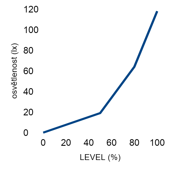
Fig. 1. The measured dependence of the light intensity on the required value
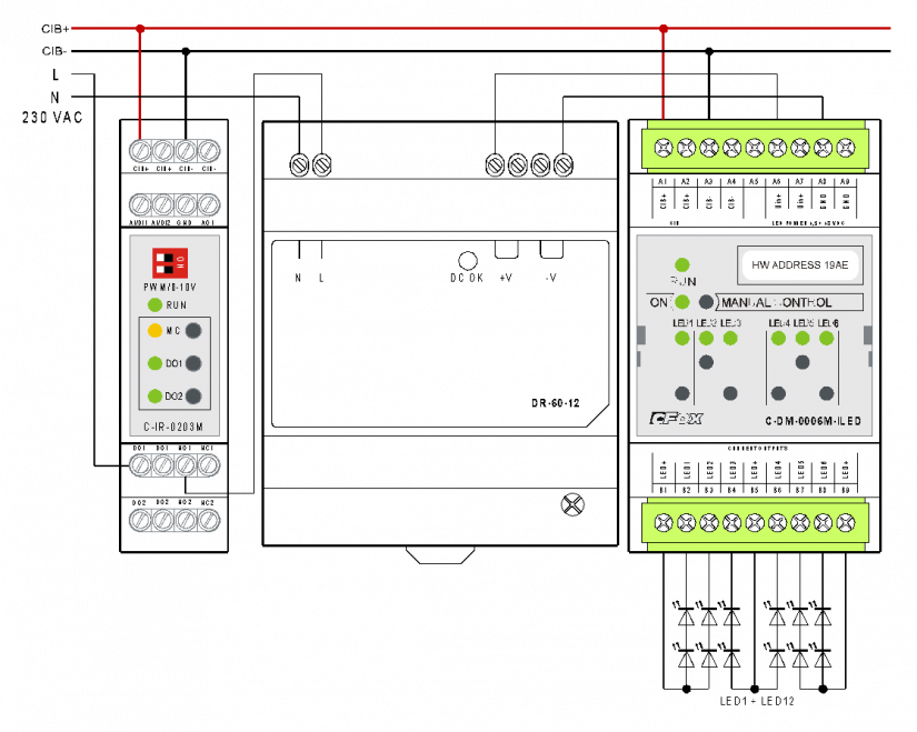
Fig. 2. An example of controlling 12 LED CREE chipsbythe C-DM-0006M-ILED dimmer, including the power supply control
Notes:
-
The LED chips layout in the module outputs in the example is optimal - on each channel there are two pieces wired in series.