
The following figure .1 shows the basic connection of the expansion modules to the basic module. Peripheral modules are interconnected including the power supply. The last module on the bus (the furthest from the basic module) must always be fitted with a terminating resistor of the TCL2 bus (see the resistor in Fig. 1.).
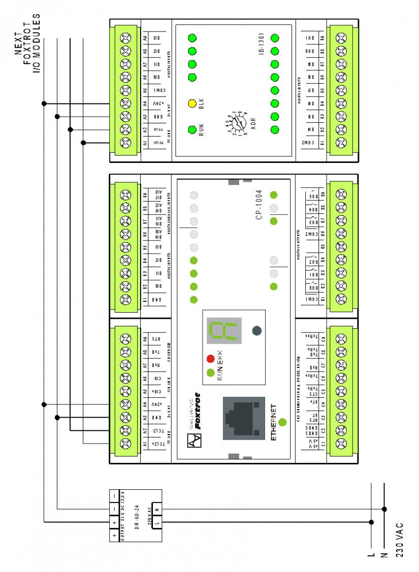
Fig. 1. The basic wiring diagram of the TCL2 bus with power supply