
If the CIB bus is installed with a risk of excess voltage influence either in the bus itself or in the connected elements (e.g. concurrence with the lightning rod, a partial installation outside the building, etc.), then surge protection MUST be used in the correct way. Only specified types of CIB surge protection are allowed. Using any other types can significantly reduce the reliability and functionality of the application.
There are two recommended types of CIB surge protection devices.
Both have identical electrical characteristics and only differ in their mechanical design:
The DTNVEM 1/CIB the 1M version on a DIN rail with screw terminals.
The DTNVE 1/CIB built-in design (e.g. in a recessed flush box) with insulated conductors outlets about 10cm long.
The DTNVE 1/CIB surge protection represents an essential element of the protection of the CIB itself. It only protects against surges that can enter the CIB installation itself. It does not replace protection of the entire control system. The main protection of each application is always the protection of the main power supply - that means a correctly designed and installed protection of the 230 V power supply voltage. Protecting the system power supply should be an integral part of each control system application. To protect the grid power supply voltage of 230 VAC, there should be applied all principles of installation of surge protection as they are commonly known and used as a “good practice”.
The DTNVEM 1/CIB is a surge protection device (SPD) in accordance with EN 61643-21 (categories A2, B2, C2, C3, D1) designed to protect the CIB against lightning currents and surges. The recommended placement is at the input line from outside into the building, as well as at interfaces to other LPZ (in accordance with EN 62305) and close to the protected equipment, so that the length of cable between the surge protection device and the protected equipment does not exceed 10m.
The DTNVE 1/CIB consists of a base and a replaceable module, which contains the protection circuits. The base is constantly connected and in case of an audit inspection or damage only the removable module is manipulated with. The base remains connected in the bus even without the removable module (the circuit is not interrupted).
The protection is designed for continuous current flow of up to 0.5 A. During the project design stage it is necessary to make sure that this current is not exceeded.
The DTNVE 1/CIB is connected from the output towards the protected equipment.
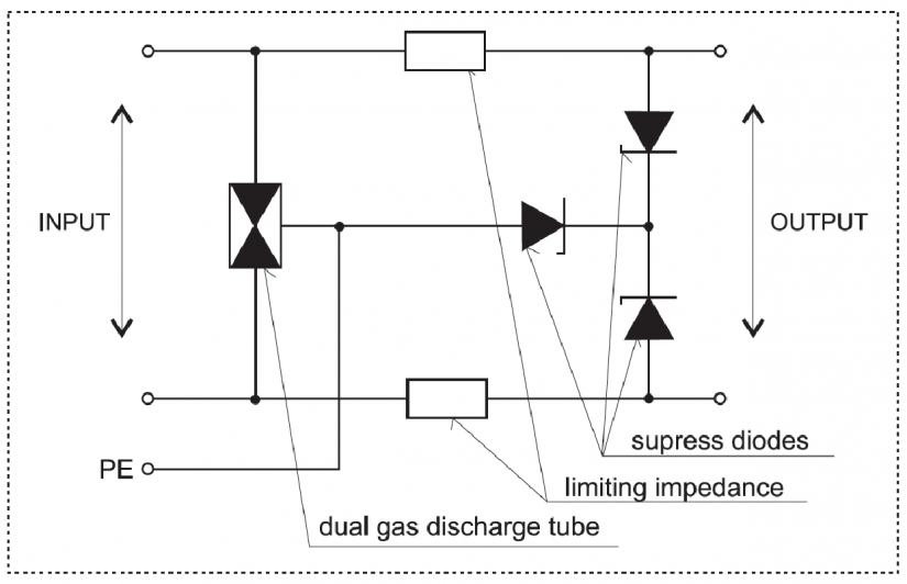
Fig. 1. Internal wiring of the DTNVE1 /CIB surge protection (it is also applicable to the DTNVE 1/CIB)
The DTNVE 1/CIB protection is always connected in front of the part of the bus that needs to be protected (i.e. you must take care of all parts of the installation leaving the ZBO1 zone or those that are in concurrence with large metal parts of the building that are in zone 0, for example the lightning conductor).
All parts of the installation that the above-mentioned statement concerns must always be protected individually.
Fig. 2 shows an example of the system installation with the CIB in a house.
The main part of the installation ③ is located inside a protected building and its protection is implemented at the 230VAC power supply input of the entire system (protection of the entire application - the central unit and the bus units).
Part ② of the units is located in the annex building (a garage), where the bus is lead by a cable buried in the ground. Here it is always necessary to install protection at each entry of cable in the building, and both parts of the installation must be protected against surges that may occur in the ground line.
One unit ① is located under the roof (e.g. a connection to an anemometer) and the corresponding bus line is positioned in parallel with the lightning conductor fixed on the outer wall. In this case, surge protection is located in a suitable place (the end of the parallel part - the example shows an unprotected unit ①,but the rest of the application is properly protected.
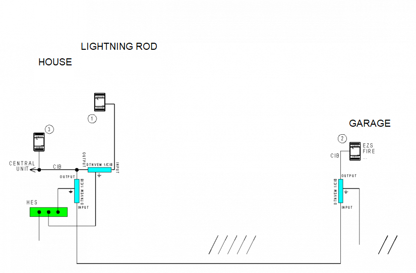
Fig. 2. Typical wiring of DTNVEM 1/CIB protection