
BDM-024-V/1-FR1-CIB
Lightning current arrester with two-stage switch protection of personal data for the bus CIB.
-
installation at the entrance to the building near the protected equipment, at the interface of zones LPZ 0 – LPZ 1 and higher
-
can also be used to protect the interfaces of control systems MaR, EZS, EPS, etc.
-
against longitudinal overvoltage (line - protective earth) rough protection and against transverse overvoltage (core - core, GND) rough and fine overvoltage protection
- removable module, coupling impedance (R - resistance), line separated from protective earth by lightning arrester
Technical parameters
|
SPD type |
D1, C2 |
|
|
Connection (input – output) |
clamp - clamp |
|
|
SPD location |
ST 1+2+3 |
|
|
Rated voltage |
Un |
24V DC |
|
Highest continuous operating voltage |
Uc |
25 VAC |
|
Highest continuous operating voltage |
Uc |
36 VDC |
|
Rated load current at 25 ° C |
IL |
1 A |
| C2 rated discharge current (8/20 µs) per core |
In |
10 kA |
|
C2 rated discharge current (8/20 µs) GND-PE |
In |
10 kA |
| C2 total discharge current (8/20 µs) of the PE core |
ITotal |
20 kA |
|
D1 impulse discharge current (10/350 µs) per core |
Iimp |
2,5 kA |
| D1 total discharge current (10/350 µs) of the PE-core |
ITotal |
5 kA |
|
C3 protective voltage level core-core mode at 1 kV/µs |
Up |
46 V |
|
C3 protection voltage level GND-PE mode at 1 kV/µs |
Up |
550 V |
| C3 protective voltage level core-GND mode at 1 kV/µs |
Up |
46 V |
|
Core-core response time |
ta |
1 ns |
|
GND-PE response time |
ta |
100 ns |
|
Core-GND response time |
ta |
1 ns |
|
Serial resistance per core |
R |
0,8 Ω |
|
Core-core frequency limit |
f |
4 MHz |
| Cross-section of connected wires fixed (min) |
0,14 mm2 |
|
|
Cross-section of connected wires fixed (max) |
4 mm2 |
|
|
Cross-section of connected wires stranded (min) |
0,14 mm2 |
|
|
Cross-section of connected wires stranded (max) |
2,5 mm2 |
|
|
Protection level |
IP 20 |
|
|
Ambient temperature range – min |
-40 °C |
|
|
Ambient temperature range – max |
70 °C |
|
|
Assembly |
DIN rail 35 mm |
|
| Meets the requirements of the standard |
ČSN EN 61643-21+A1,A2 |

Fig. 1. Dimension of module
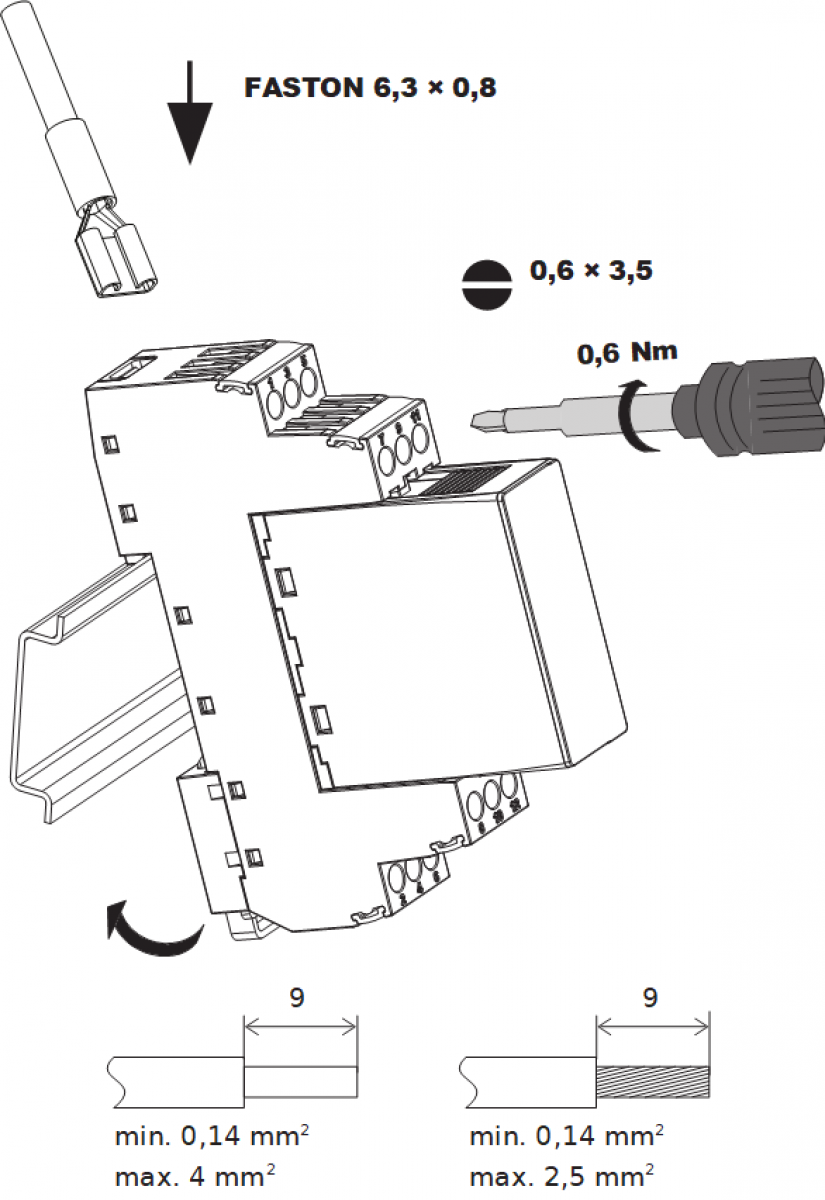
Fig. 2. Module assembly
Notes:
-
The terminal screws are grooved 3,5 x 0,6 mm, tightening torque 3,5 Nm.
- Min. wire cross section is 0,14 mm2, max. cross section for solid wire is 4 mm2 and 2,5 mm2 for stranded wire with sleeve.
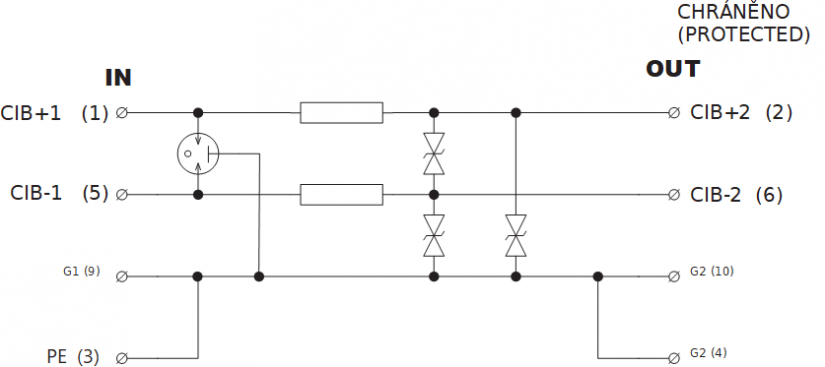
Fig. 3. Internal connection of the module