
The CF-1141 master module provides the power for and operation of two CIB buses (branches), each with a maximum of 32 connected peripheral modules (units). The CF-1141 provides identification, addressing, configuration and operation of connected peripheral modules; it also provides data processing and their transmission to the Foxtrot basic module. It is connected by the TCL2 system bus to the basic module. Up to 4 external CF-1141 master modules can be connected to the Foxtrot basic module. The configurations and any module settings is provided from the Mosaic programming environment, or from the parametrization environment FoxTool, both running on PC. The master module is equipped with diagnostics, which makes it possible to obtain information about the communication status of each bus module, as well as about the number of communication errors, etc. The CF-1141 is also equipped with terminals for connecting the backup battery ensuring power supply to its own master module and both CIB buses during a power failure of the main source. All inputs and outputs are protected by a reversible electronic fuse against short circuits.
The front panel of the module contains a two-colour LED indicator (green LED indicates the bus operation, red means bus communication errors) and a rotary switch, which serves for setting master module address.
The master module is powered from a 24 VDC or 27.2 VDC source (for backup). It also includes power supply decoupling circuits for powering both CIB buses, so no external decoupling modules are required. The module power input is the sum of power inputs of all peripheral modules in both CIB buses. The same requirements should be applied to power supply of the CP-1000 basic modules.
Maximum load of each CIB bus (branch) is 1 A.
The power supply has to be chosen with respect to the consumption of the master module plus both CIB branches full of modules. Both the master module power supply and the total consumption of all connected and powered CFox peripheral modules must have a big enough capacity for this consumption of power.
If the CF-1141 is located in the same control panel as the basic module, it can be powered from a common (and jointly backed) source (then the backup battery should be connected only to one of the modules - e.g. the Foxtrot basic module).
The CF-1141 module is connected to the Foxtrot basic module by the TCL2 system bus (Chapter 3.3).
The CF-1141 basic connection is shown in the following figure.
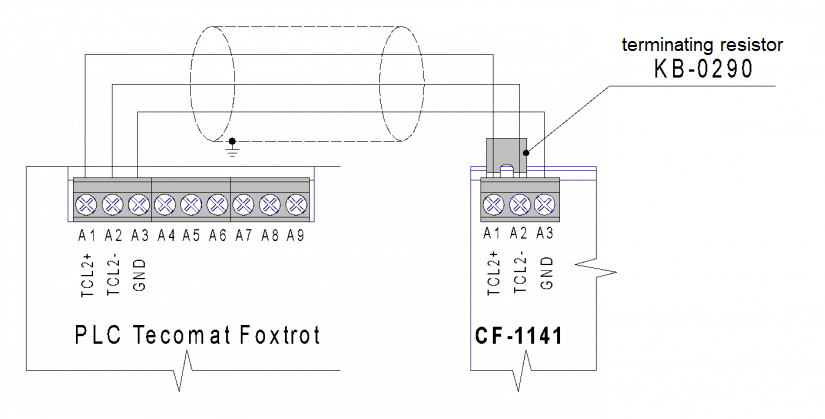
Fig. 1. Connecting the CF-1141 to the Foxtrot basic module
A complete example of the CF-1141 connection to the CP-1004 is presented in Chapter 3.3.4.
A backup battery can also be connected to the CF-1141 module, as shown in the Fig. below. It is then possible to power the basic module from the output BACKUP (terminals B8 and B9), but only if the total power consumption of the assembly conforms to the PS2-60/27 source.
It is also possible to power and provide backup to the CF-1141 module and the Foxtrot basic module (e.g. the CP-1000) separately and independently - then both modules are connected only by the TCL2 system bus.
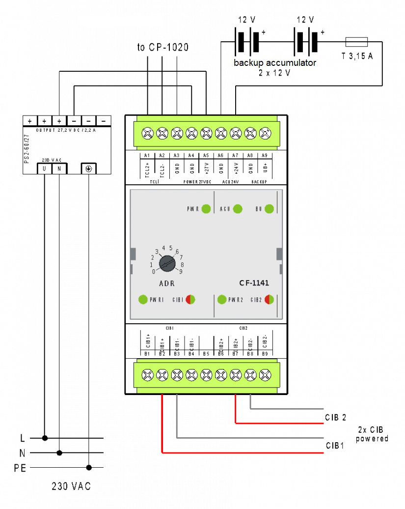
Fig. 2. The basic CF-1141 connection with a backup
Notes:
-
The power supply must be stabilized 27.2 VDC, fulfilling the SELV requirements and designed to charge the connected batteries, usually the PS2-60/27. The CF-1141 power consumption is the sum of the module’s circuits (typically 0.5 W) and the total power consumption of all CFox modules connected to both CIB branches.
-
In the terminal block B there is an output of both CIB branches including the power supply with a maximum current of 1 A for each branch.
-
The backup batteries that we recommend are sealed lead-acid type, typically with a capacity from 7 Ah to 28 Ah (depending on the desired backup time and backup power system components).
-
The BACKUP output (terminals A8, A9) can be used for powering the basic module, if it is in the same distribution cabinet as the backed-up master CF-1141 (the backup battery is in this case connected only to the CF-1141, and at the same time it is a backup for the basic module). Total consumption of the whole assembly must not be exceeded, and it must conform to the power output of the PS2-60/27 source with a maximum total power take off at 2.2 A)