
The operator´s panels ID-31 and ID-32 are designed to cooperate with the TECOMAT TC700 systems and Foxtrot.
User screens are created in the Mosaic programming environment with the Webmaker tool, and are therefore identical with the sites accessible via the web server.
The panel has a backlit LCD touch screen with the resolution of 480x272 pixels. The power supply voltage of the panel is 24 VDC and it is connected either to terminals A3, A4, or the panel can be powered via the Ethernet interface cable; the 24 V supply should be connected to the unused pairs 4/5 and 7/8. In this case, the polarity is irrelevant.
Communication between the control system and the ID-3 panel takes place via the Ethernet 100Base-TX interface, or via a serial line with the RS-485 interface using the EPSNET protocol.
The ID-31 panel is designed to be mounted on the wall; it should be attached on the KU 68 wiring box.
The ID-32 panel is designed for built-in mounting in the switchboard door, and the like.
Basic parameters of the ID-31 and ID-32 panels
|
Protection (after assembly) in accordance with ČSN EN 60529 |
the front panel IP50, the whole product IP20 |
|
Supply voltage |
power supply SELV typically 24 VDC |
|
Internal protection |
No |
|
Power consumption |
maximum 4 W |
|
Galvanic isolation of power supply from internal circuits |
No |
|
Maximum weight |
0.3 kg |
|
Dimensions of ID-31 |
135 x 91 mm |
|
ID-32 |
133 x 91mm |
|
Display |
colour TFT LCD |
|
Diagonal |
4.3" |
|
Resolution |
480 × 272 pixels |
|
The number of colours |
16.7 million |
|
Back light |
LED |
|
Lifetime |
typically 20,000 hours |
|
Touch screen |
ID-31 capacitive |
|
|
ID-32 resistive |
|
Power supply connector 24V and RS-485 |
Wire cross-section 0.5 ÷ 1.5 mm2, removable connector |
The ID-31 panel is designed for wall mounting in the KU 68 flush-box.
On the rear side the panel has a metal cover with IP20 protection. On the bottom side of the panel are placed two screws. If you loosen them, a sheet metal support will be released - it should be screwed on the flush box. Then the panel can be hung on the metal sheet support from the top, pushed to the wall and secured by lightly tightening the two screws.
Connecting the cables (Ethernet, 24 VDC power supply) is identical with the ID-32 panel (see the figure below).
The ID-32 panel is designed for built-in mounting, the front panel is made of plastics. The rear of the panel is protected by a cover metal sheet with IP20 protection.Four metal clamps with fastening screws serve for mounting. They are incorporated in the panel, which they fasten by turning 90 degrees and then tightening the screws.

Fig. 1. Wiring the connectors and connecting the power supply to panels ID-32, ID-31 and ID-36.
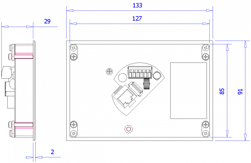
Fig. 2. Mechanical dimensions and placement of the ID-32 module connectors
Notes:
-
On the rear side of the panel is the RJ-45 connector for connecting a standard patch cable and the RS-485 (TCL2) removable connector with 24 VDC power supply and a variable interface.
-
Alternatively, the panel can be powered via the Ethernet interface cable: the 24 V supply voltage should be connected to the unused pairs 4/5 and 7/8, and the polarity in this case is irrelevant. Suitable passive modules for power supply injection l (or Splitter) can be obtained in computer shops (they are often referred to as PoE modules, although they don´t represent the standard Power over the Ethernet).
-
The mounting hole dimensions should be 128 x 86 mm.
-
The operators´ panels must not be exposed to direct sunlight.