
The OT-1651 expansion module contains four unipolar analogue outputs. Each can be used either as a voltage or a current output. Both types of loads are connected against the common terminal - signal ground (AGND). The resolution is 12 bits. The analogue outputs are galvanically isolated from the module power supply and the TCL2 communication. The output circuits require for their function a separate external 24 VDC power supply. The current loop status is indicated on the module panel.
The analogue outputs AO0 ÷ AO3
|
The type of output |
voltage active |
current active |
|
Output range |
0 ÷ 10 V |
0 ÷ 20 mA |
|
Maximum output value |
105 % of the output range upper limit |
|
|
Maximum output current |
10 mA |
- |
|
The short circuit current |
12 mA |
- |
|
The current loop resistance |
- |
0 ÷ 600 Ω |
Basic parameters
|
Supply voltage (communication part, the A4 terminal) |
24 VDC, +25 %, –15 % |
|
A typical power consumption (communication part) |
0.3 W |
|
The supply voltage of output circuits (A6 terminal) |
24 VDC, - 25 %, + 20 % 1. |
|
The consumed current of the output section |
max. 135 mA |
|
Max. total module power loss |
4.4 W |
Notes:
-
When only current outputs are used, lower supply voltage + VAO can be applied to reduce the power losses of the module. The voltage value is calculated from the largest current loop resistance x maximum current (21 mA) +6 V
The connectors of the module are standard removable ones with a cage terminal in the removable part with 5.08 mm spacing. A flat-head screwdriver with the tip width of 3.5 mm is recommended for manipulation with the terminal. Detailed parameters of the connectors are specified in Chapter 13.3.1 Connectors with screw terminals, spacing 5.08 mm, modules on a DIN rail.
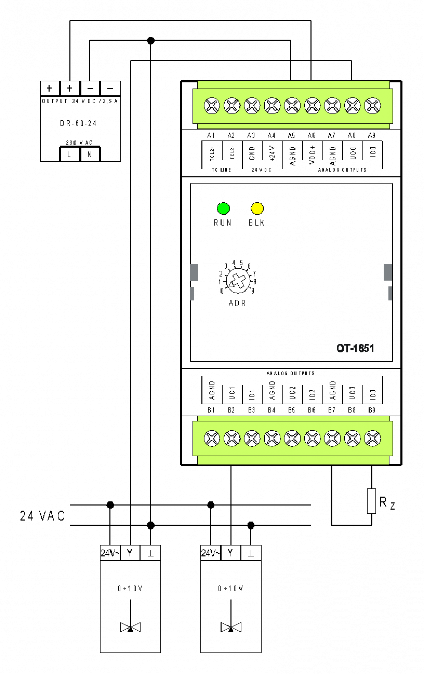
Fig. 1 An example of the OT-1651 module wiring.
Wiring notes:
-
The analogue outputs (voltage and current) have a common AGND terminal.
-
A power supply for output circuits must always be used; the source in the example is DR-60-24. When galvanic isolation is not applied, it is possible to use for i output circuits a power supply source for powering the system (then you should connect terminals A4 with A6 and A3 with A5).