
The IT-1604 expansion module has substituted the previous IT-1601 module.
The module contains 8 analogue inputs with a common terminal and 2 analogue outputs with a common terminal. The inputs are universal, independently configurable as voltage, current inputs, two-wire connection of passive resistance sensors. With 16-bit resolution, the module provides the processing of the values measured, conversion to engineering units, etc. The analogue outputs have 10-bit resolution, the voltage is 0 ÷ 10V. The analogue inputs and outputs are galvanically isolated from the internal circuits and the status of each input is indicated on the module panel.
The analogue inputs AI0 ÷ AI7
|
Voltage ranges |
0 ÷ +10 V 0 ÷ +5 V 0 ÷ +2 V 0 ÷ +1 V 0 ÷ +0.5 V |
|
|
Current ranges |
0 ÷ 20 mA 4 ÷ 20 mA 0 ÷ 5 mA |
|
|
Passive temperature sensors |
Pt100, W100 = 1.385 and 1.391 Pt1000, W100 = 1.385 and 1.391 Ni1000, W100 = 1.617 and 1.500 KTY81-121 NTC thermistor 12 kΩ |
–90 ÷ +400 °C –90 ÷ +400 °C –60 ÷ +200 °C –40 ÷ +125 °C –40 ÷ +125 °C |
|
Resistance ranges |
0 ÷ 100 Ω (the OV100 resistance transmitter) 0 ÷ 1 kΩ (the OV1000 resistance transmitter) 0 ÷ 2 kΩ 0 ÷ 200 kΩ |
|
|
Input impedance in signal range: |
> 100 kΩ (ranges 0.5 V, 1 V and 2 V) > 50 kΩ (ranges 5 V and 10 V) |
|
|
Reference voltage (Vref) |
10 V |
|
|
Internal resistance for current ranges |
100 Ω |
|
|
Measurement time of one channel |
typically 65 ms (70 ms for measurement of temperature sensors) |
|
|
Recovery time value of each channel |
typically 500 ms (600 ms for measurement of temperature sensors) |
|
The analogue outputs AO0, AO1
|
Output range |
0 ÷ 10 V |
|
Maximum output value |
105 % of the output range upper limit |
|
Maximum output current |
10 mA |
|
Maximum load capacity |
50 nF |
Basic parameters
|
Supply voltage |
24 VDC, +25%, –15% |
|
Typical power consumption |
2.2 W |
|
Maximum power consumption |
2.4 W |
The connectors of the module are standard removable ones with a cage terminal in the removable part with 5.08 mm spacing. A flat-head screwdriver with the tip width of 3.5 mm is recommended for manipulation with the terminal. Detailed parameters of the connectors are specified in Chapter 13.3.1 Connectors with screw terminals, spacing 5.08mm, modules on a DIN rail
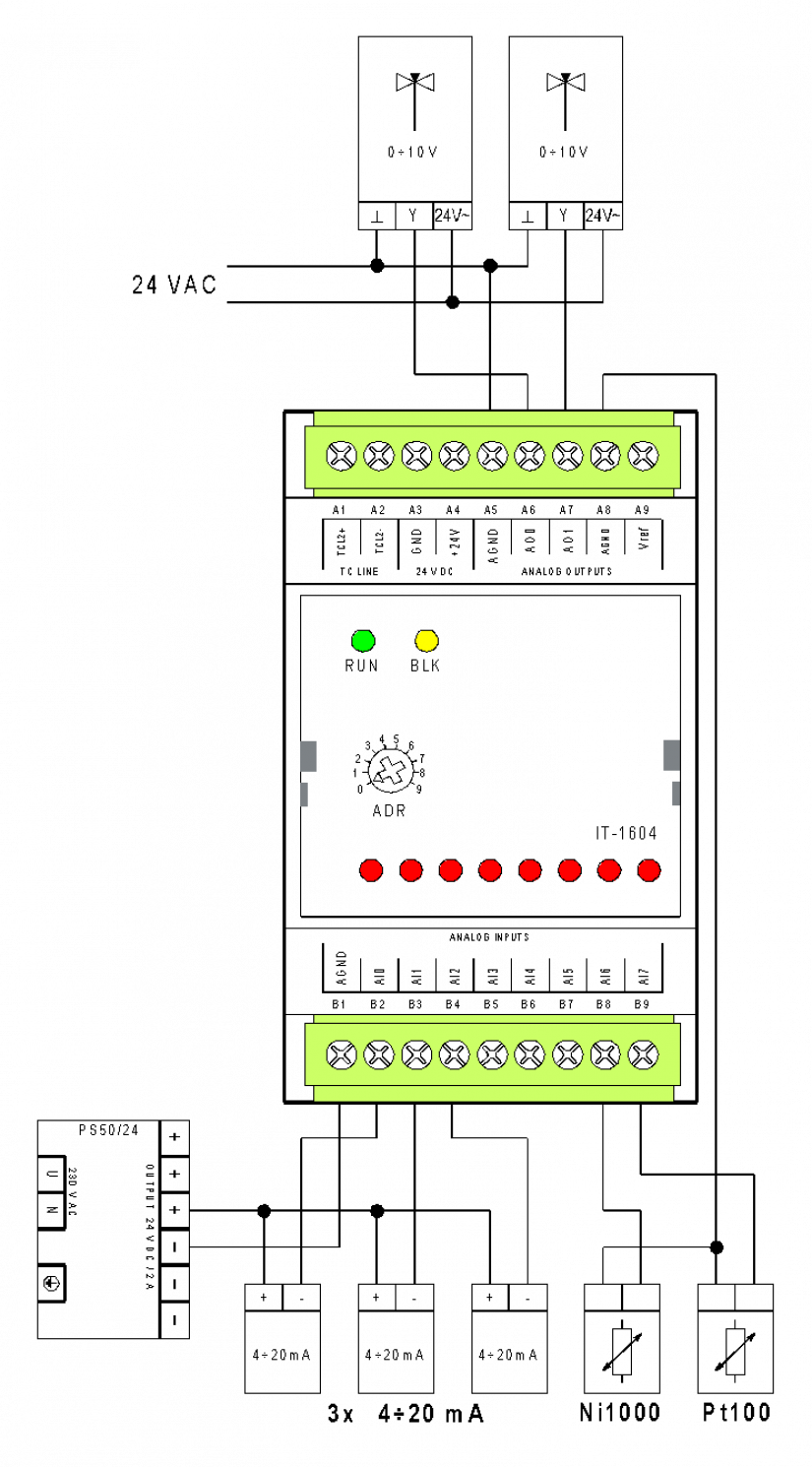
Fig. 1 The basic wiring diagram of the IT-1604 module
Wiring notes regarding the following figure .1:
-
The analogue inputs and outputs have a common AGND terminal.
-
In order to improve measurement accuracy, it is recommended to connect the input signals (sensors) in accordance with the example, i.e. to use the A8 terminal as a common AGND terminal for the measurement of passive resistance sensors.
-
There is an exact +10.0 V voltage in the Vref terminal, which is available for powering passive resistance sensors (using an external serial resistor).
-
The passive resistance sensors with a two-wire connection are powered by an internal 10V supply via serial resistors 7K5 fitted inside the module. (N.B.: This is a change compared to the IT-1601). For backward compatibility with the IT-1601 module it is also possible to use external power supply of sensors via 7K5 serial resistors from the Vref terminal. In this case, the resistor is mounted outside the module in the control panel. The other end of the sensor should be connected to AGND terminal no. A8(!) (It is recommended to use the MT-1691 module), and set a mode compatible with the IT-1601 in the configuration.
-
The precision of the 7K5 resistor (if fitted outside) has a key impact on the accuracy of measurement of resistive sensors. The resistors used in the MT-1691 module have a basic accuracy of 0.1 % and the minimum temperature coefficient is 25 ppm.
-
The current ranges (20 mA, etc.) are switched from the Mosaic programming environment (the module is not fitted with internal jumpers).