
The IR-1501 expansion module is designed to scan up to four 24 VDC binary signals with a common terminal (plus or minus, according to the wiring), type 1. The module contains 8 relay outputs with a switching contact and a common terminal.
The DI0 ÷ DI3 inputs allow the implementation of special functions identical with the inputs of the CP-1004 basic module (the functions and input modes are identical with the DI0 ÷ DI3 inputs of the CP-1004 module). For detailed information and examples of connections, see Chapter 2.7.3.1 Special functions of binary inputs in the CP -1004 module.
The relay outputs can switch max. 230 VAC, 3 A (the current via a common terminal is max. 10 A).
The inputs are galvanically isolated from the internal circuits (power supply and communication to the basic module) and the inputs are separated from the outputs; the status of each input and output is indicated on the front panel.
The binary inputs DI0 ÷ DI3
|
|
DI0 ÷ DI3 |
|
Input type |
Type 1 |
|
Input voltage for Log. 0 |
max. +5 VDC |
|
Input voltage for log.1 |
min. +15 VDC, typically +24 VDC, max. +30 VDC |
|
Input current in log. 1 |
typically 10 mA |
|
The minimum width of the captured pulse |
50 μs |
The counter inputs DI0 ÷ DI3
|
Max. input frequency |
5 kHz |
|
The minimum width of the captured pulse |
50 μs |
|
Incremental sensor: |
|
|
Max. frequency of symmetric signal V, G |
1.25 kHz |
|
Pulse width (V, G, NI, MD) |
min. 50 µs |
|
Pulse length, period and phase shift measurement: |
|
|
Input frequency |
0.1 ÷ 5,000 Hz |
|
Pulse width |
50 ÷ 10,000,000 µs |
Basic parameters
|
Supply voltage |
24 VDC, +25 %, –15 % |
|
Typical power consumption |
2.2 W |
|
Maximum power consumption |
3 W |
The relay outputs DO0 ÷ DO7
Outputs with a common terminal, continuous 3 A output current, inrush 5 A, max. continuous current via a common terminal COM2 is 10 A, for more detailed information on relay contacts, see Chapter 13.4.1 Relay 5A, the Foxtrot basic module and peripheral modules CFox
The connectors of the module are standard removable ones with a cage terminal in the removable part with 5.08 mm spacing. A flat-head screwdriver with the tip width of 3.5 mm is recommended for manipulation with the terminal. Detailed parameters of the connectors are specified in Chapter 13.3.1 Connectors with screw terminals, spacing 5.08 mm, modules on a DIN rail
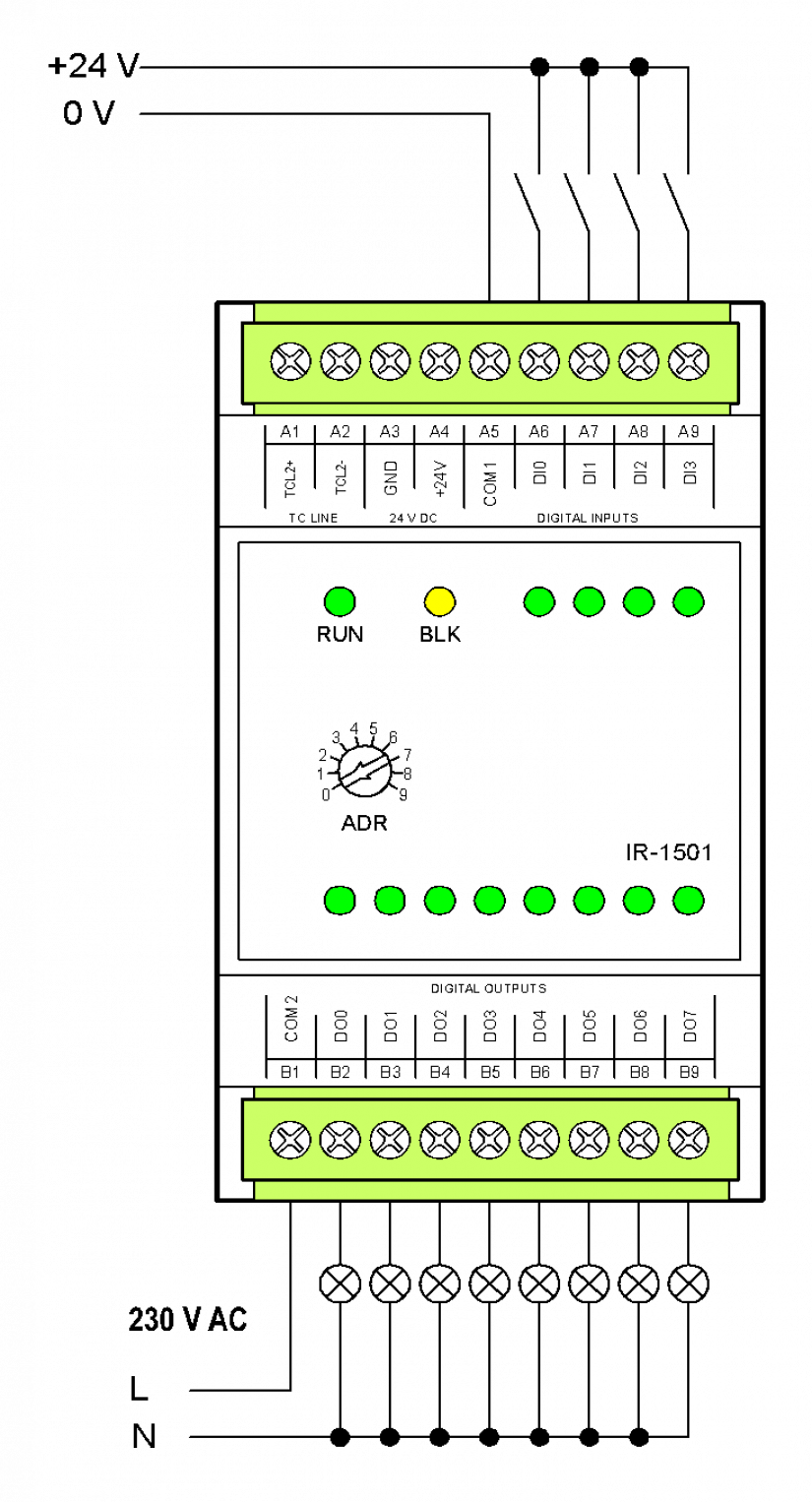
Fig. 1 The basic wiring diagram of the IR-1501 module
Wiring notes:
-
The DI0 ÷ DI3 inputs enable the implementation of special functions (connection of incremental encoders, counters, etc.); for detailed information, see Chapter 2.7.3.1.
-
The relay outputs are separated from other circuits by 4 kV isolation.
-
The inputs in the example are connected with a common negative terminal.