
The OS-1401 expansion module contains 12 semiconductor outputs with a switching contact and a common positive terminal (VDO+).
The DO0 ÷ DO3 outputs allow switching max. 24 VDC, 2 A per output (total current load of all four outputs must not exceed 4.4 A), the DO4 ÷ DO11 outputs allow switching max. 24 VDC, 0.5 A per output. The outputs are galvanically isolated from the internal circuits (power supply and communication to the basic module) and groups of outputs are galvanically connected, they have common power supply and shared a positive terminal (VDO +); the status of each output is indicated on the front panel of the module.
The Binaryoutlets D00 ÷ DO11
|
|
DO0 ÷ DO3 |
DO4 ÷ DO11 |
|
The type of output |
Transistor |
|
|
Common cable |
plus |
|
|
The range of switching voltage |
9.6 ÷ 28.8 VDC |
|
|
Switching current |
max. 2 A |
max. 0.5 A |
|
The current via a common terminal |
max. 4.4 A |
max. 4.5 A |
|
Initial peak current limitation |
typically 7.5 A (switching off time typically 4 ms) |
|
|
Short circuit current limitation |
typically 4 A |
|
|
Reverse polarity protection |
yes |
|
Basic parameters
|
Supply voltage |
24 VDC, +25 %, –15 % |
|
Typical power consumption |
1 W |
|
Maximum power consumption |
2 W |
The connectors of the module are standard removable ones with a cage terminal in the removable part with 5.08 mm spacing. A flat-head screwdriver with the tip width of 3.5mm is recommended for manipulation with the terminal. Detailed parameters of the connectors are specified in Chapter 13.3.1 Connectors with screw terminals, spacing 5.08 mm, modules on a DIN rail.
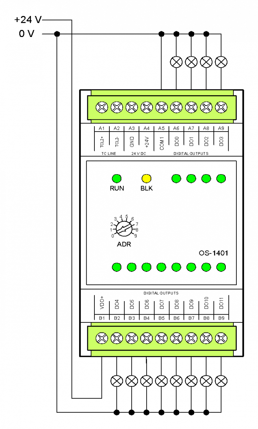
Fig. 1 The basic wiring diagram of the OS-1401 module
Wiring notes:
-
The outputs are switched against a common VDO + terminal (max. current via 9 A terminal).
-
The outputs are implemented via semiconductor switches with internal protection against current and temperature overloading. To increase the resistance and lifetime of the system, it is important to treat the switching loads by appropriate interference suppressors (see Chapter 13.7.3 Interference suppression, application of suppression measures).
-
A 24 VDC power supply connected to the VDO+ and the COM1 terminals is necessary for proper function of the output sensors!