
The CP-1003 basic module features eight multi-purpose inputs, each of which can be used either as an analogue input (voltage, current or a passive temperature sensor) or a binary 24 V input, with eight fast binary inputs featuring adjustable decision level, four analogue outputs ± 10 V, eight relay outputs and four high-speed transistor outputs allowing direct connection of DC or stepper motors.
The basic CP-1003 module is fitted with the Ethernet interface, with up to 4 serial ports (the first one with a fixed RS-485 interface, others with an additional slot for an optional submodule) and two TCL2 system interfaces for connecting expansion modules, which increase the number of I/O in the system.
A standard configuration of the module is in a 9M housing on a DIN rail (for the housing dimensions, see Chapter 13.2.1 9M housing on a DIN rail), and it is fitted with six removable terminal blocks.
The I/O layout:
Power supply 24 VDC, power consumption max. 10 W (information on power supply see Chapter 2.2)
AI0 ÷ AI7 7 analogue inputs, galvanically isolated with optional binary input:
-
for the ranges see the Table below
DI8 ÷ DI15 8 binary inputs, with galvanic isolation, for the ranges see the Table below
AO0 ÷ AO3 4 analogue outputs with galvanic isolation, range -10 ÷ 10 V
DO0 semiconductor output, galvanically isolated from other circuits, 1 A, 230 V, SSR, the output can be set to PWM mode
DO1 ÷ DO6 6 relay outputs, with galvanic isolation from other circuits, 3 A on the output
DO7 relay output for continuous 10 A (16 A contact)
DO8 ÷ DO11 4 semi-conductor 24 V outputs, for the parameters see the Table below
The Ethernet 10/100 Mbit (a standard RJ-45 connector), with galvanic isolation from other circuits, see Chapter 2.4.1
CH1 Serial channel, with fixed RS-485interface, without galvanic isolation see Chap. 2.3.1
CH2 Serial channel, with a possibility of fitting with standard submodules, see Chapter 2.3.3
Basic parameters
|
Supply voltage (SELV) |
24 VDC, +25%, –15% |
|
Power consumption of the module |
max. 10 W |
|
Connection/max. wire cross-section |
removable terminal blocks, max. 2.5 mm2 (power supply, DO, CH1, TCL2), max. 1.5 mm2 (DI, AI, AO, CH2) |
|
The analogue inputs |
AI0 ÷ AI7 |
|
Galvanic isolation from internal circuits |
yes (galvanic connection only with analogue outputs) |
|
Temperature sensor Pt1000, W100=1,385 or 1,391 |
-90 °C ÷ +400 °C |
|
Temperature sensor Ni1000, W100=1.500 or 1.617 |
-60 °C ÷ +200 °C |
|
Temperature sensor NTC 12k |
-40 °C ÷ +125 °C |
|
|
-55 °C ÷ +125 °C |
|
Resistance ranges |
0 ÷ 1 kΩ 0 ÷ 2 kΩ 0 ÷ 200 kΩ |
|
Voltage ranges |
0 ÷ 0.5 V 0 ÷ 1 V 0 ÷ 2 V 0 ÷ 5 V 0 ÷ 10 V |
|
Current ranges |
0 ÷ 20 mA 4 ÷ 20 mA |
|
Input resistance for current ranges |
100 Ω |
|
Input resistance for voltage ranges |
> 20 kΩ (ranges 10 V, 5 V) |
|
Internal voltage for power supply of resistance sensors |
7.27 V |
|
Conversion time of channel |
typically 80 μs |
|
Recovery time of each channel value
|
typically 480 μs |
|
Analogue outputs |
AO0 ÷ AO3 |
|
Output range |
-10 ÷ 10 V |
|
Maximum output value |
105 % of the output range upper limit |
|
Maximum output current |
10 mA |
|
Maximum load capacity |
50 nF |
|
Galvanic isolation from internal circuits |
yes 1 |
1 The AO0 - AO3 outputs have a common ground with the DI0/AI0 - DI7/AI7 inputs.
|
Binary inputs |
DI0 ÷ DI7 |
DI8 ÷ DI15 |
|
Galvanic isolation from internal circuits |
yes (galvanic connection only with analogue outputs) |
|
|
External power supply |
- |
Yes, VDI = 5 ÷ 30 VDC |
|
Input voltage for log. 0 |
max. +5VDC |
max. 0.25 * VDI |
|
Input voltage for log. 1 |
min. +15 VDC typically +24 VDC max. +30 VDC |
min. 0.6 * VDI typically VDI max. +30 VDC |
|
Input current in log. 1 |
typically 5 mA |
typically 5 mA at 24 V |
|
The minimum width of the captured pulse |
- |
5 μs |
Notes:
-
The DI0 - DI7 inputs, which can also be used as analogue inputs AI0 - AI7, are galvanically isolated from the internal PLC circuits; they have a common ground with the AO0 - AO3 analogue outputs. The DI0 - DI7 inputs work as binary only when they are not used for analogue measurements (valid for each input independently of the others).
-
The DI8 - DI15 inputs can be used as inputs for counters. These inputs are arranged in two groups of four with separately terminated power supply for each galvanically isolated tetrad. Each of these four inputs can thus operate with different voltage levels in the range of 5-24 V, which makes it possible also to connect IRC sensors with 5 or 12 V power supply. Even when they are used as inputs for counters, the DI8 - DI15 inputs can be concurrently used as binary.
-
The DI8 - DI15 inputs make it possible to switch on the function of capturing short pulses. This function extends the selected level of input signal up to the PLC cycle. In this way you make sure that no single pulse shorter than the PLC cycle will be lost in the input.
-
If any of the four inputs is used for an object of the relevant counter, the function of capturing short pulses cannot be used in any of the four inputs.
The DI8 ÷ DI15 counter inputs
|
Input frequency – a fast unidirectional counter |
100 kHz |
|
Input frequency – a standard counter |
5 kHz |
|
The IRC symmetric frequency sensor (tracks V, G) |
100 kHz |
|
Maximum metering rate |
400,000 increments |
|
Pulse width |
min. 5 µs |
|
Pulse length, period and phase shift measurement: input frequency Pulse width |
0.1 ÷ 5,000 Hz 50 to 10,000,000 µs |
Notes:
-
Conventional counters can be operated with the signal frequency of 5 kHz. In an unidirectional counter and IRC modes, the hardware support is enabled and the counter can be operated at a high speed mode with the signal frequency of up to 100 kHz.
The DO8 ÷ DO11 binary outputs
|
The number of outputs |
4 (in one group) |
|
Galvanic isolation from internal circuits |
yes |
|
Outputs type |
Semiconductor output, a half-bridge (push-pull) |
|
Switching voltage |
10 - 32 V |
|
Switching current |
each output continuously 2.7 A, in pulse mode 4 A |
|
at 25 °C ambient temperature at about 50 °C ambient temperature |
IDO8 + IDO9 + IDO10 + IDO11 < 6 A IDO8 + IDO9 + IDO10 + IDO11 < 4 A |
|
Residual current (blocked outputs) |
max. 2 mA |
|
Output resistance |
typically 0.3 max. 0.6 |
|
Switching/opening duration |
typically 1.6/0.6µs |
|
Short-circuit protection |
yes |
The PWM DO8 ÷ DO11 outputs
The DO8 - DO11 binary transistor outputs can also be operated in the pulse-width modulation (PWM) mode. It is possible to set a common pulse repetition periodfor these outputs as a part of the initialization. The pulse width itself is variable and is determined separately for each output by the value of the corresponding object variable PWM output These four outputs can be blocked in pairs from the user program.
The relay outputs of the CP-1003 module
| The DO0 SSR (semiconductor relay) output, continuous current in the output 0,7 A, inrush 1 A. The output is fitted with an SSR relay switching at zero It can be used as a PWM output to control e.g. the revolutions of small asynchronous motors (fans, circulation pumps) | 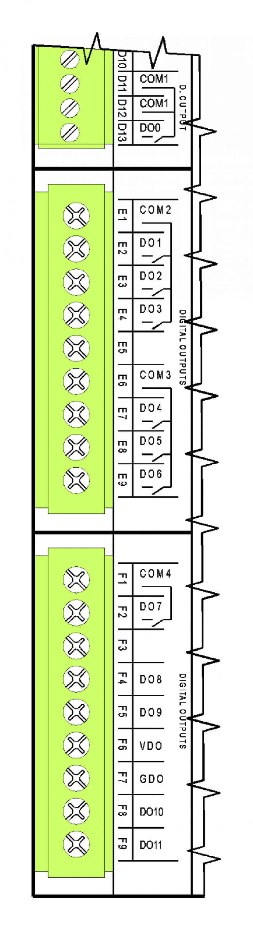 |
| Isolation voltage among groups of outputs and from other circuits is 3750 VAC, i.e. safe isolation of circuits | |
| The DO1 ÷ DO3 outputs with a common terminal, continuous current in the 3 A output, inrush 5 A, max.continuous current in the common terminal COM2 is 10 A, more detailed information on the relay contacts. | |
| Isolation voltage among groups of outputs and from other circuits is 3750 VAC, i.e. safe isolation of circuits | |
| The DO4 ÷ DO6 outputs with a common terminal, continuous current in the 3 A output, inrush current 5A, max.continuous current in common terminal COM3 is 10 A, more detailed information on relay contacts. | |
| Isolation voltage among groups of outputs and from other circuits is 3750 VAC, i.e. safe isolation of circuits | |
| The DO7 relay continuous current 10 A, inrush overloading 160 A < 20 μs, detailed information about relays in Chapter 13.4.2 | |
| Isolation voltage among groups of outputs and from other circuits is 3750 VAC, i.e. safe isolation of circuits | |
| The DO8 ÷ DO11 semiconductor outputs with common power supply on VDO a GDO terminals, continuous current in the output 2.7 A, the outputs require power supply for their proper function (typically 24 VDC). |
For principles of protection and usage for capacitive and inductive loads, see Chapter 13.7.1 Protection of output elements (relays,...).
Terminal blocks of the basic module are connectors witha cage terminal with spacing 5.08 mm. Detailed parameters of the terminals are specified in Chapter 13.3.1 Connectors with screw terminals, spacing 5.08 mm, modules on a DIN rail
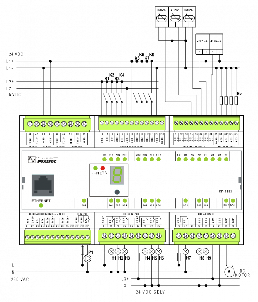
Fig. .1 Example of connecting the CP-1003 module.
Notes:
-
The RS-485 (CH1) interface is firmly terminated in the module with appropriate impedance and it must always be at the end of the RS-485 line (the same applies for the TCL2 interface in the Foxtrot basic module).
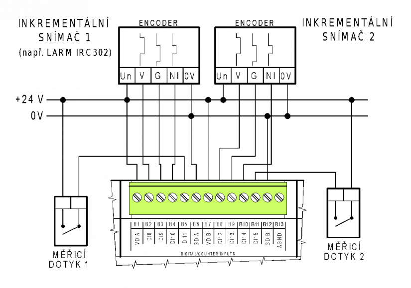
Fig. 2 An example of connecting incremental encoders to the CP-1003