
The CP-1091 is the basic module of the Foxtrot control system. The standard version is in a 9M housing on a DIN rail (for the housing dimensions, see Chapter 13.2.1 9M housing on a DIN rail), and it is fitted with six removable terminal blocks.
The I/O layout:
Power supply 24 VDC, power consumption max. 8 W (information on power supply see Chapter 2.2)
AI0 ÷ AI5 6 analogue inputs, without galvanic isolation with an optional function of binary input:
-
ranges: Ni1000, Pt1000, OV1000, KTY81-121, binary input (potential free contact)
DI6 ÷ DI11 6 binary inputs, without galvanic isolation: a standard binary 24 VDC input, counter input (e.g. connecting the S0 signals)
DI12 (HDO) binary input 230 VAC, galvanically isolated (e.g. ripple control)
AO0 ÷ AO1 2 analogue outputs, without galvanic isolation, range 0 ÷10 V
DO0 ÷ DO8 9 semiconductor output switches with 24 VDC, 0.5 A, optional PWM function and functions for controlling power SSR relays (electrical heating control)
DO9 ÷ DO11 3 relay 16 A continuous current, 80 A inrush current, each output is individually terminated
ETH Ethernet 10/100 Mbit (a standard RJ-45 connector), with galvanic isolation from other circuits, see Chapter 2.4.1
CH1 Serial channel, with fixed RS-485, without galvanic isolation, see Chap. 2.3.1
CH2 Serial channel, with a possibility of fitting with standard submodules, see Chapter 2.3.3
|
Binary inputs |
DI0 ÷ DI5 |
DI6 ÷ DI11 |
DI12 |
|
Input voltage for log. 0 (open contact) |
min. +2.3 VDC max. +12 VDC |
max. 10 V |
max. 120 VAC |
|
Input voltage for log. 1 (switched contact) |
max. +1 VDC |
min. 12 V |
min. 200 VAC max. 250 VAC |
|
Input current in log. 1 |
typically 1.7 mA |
typically 5 mA |
typically 5 mA |
|
The minimum width of the captured pulse |
20 ms |
2 ms |
- |
|
The analogue inputs |
AI0 ÷ AI5 |
|
Temperature sensor Pt1000, W100=1.385 or 1.391 |
-90 °C ÷ +270 °C |
|
Temperature sensor Ni1000, W100=1.500 or 1.617 |
-60 °C ÷ +155 °C |
|
Temperature sensor KTY81-121 |
-55°C ÷ +125 °C |
|
Temperature sensor NTC 12k |
-40 °C ÷ +125 °C |
|
Resistance ranges |
0 ÷ 2 kΩ |
|
0 ÷ 200 kΩ |
|
|
Internal voltage for power supply of resistance sensors |
8.34 V |
|
Conversion time of channel |
typically 50 μs |
|
Recovery time of each channel value |
typically 650 μs |
|
Analogue outputs AO0 ÷ AO1 |
|
|
Output range |
0 ÷ 10 V |
|
Maximum output value |
105 % of the output range upper limit |
|
Maximum output current |
10 mA |
|
Maximum load capacity |
50 nF |
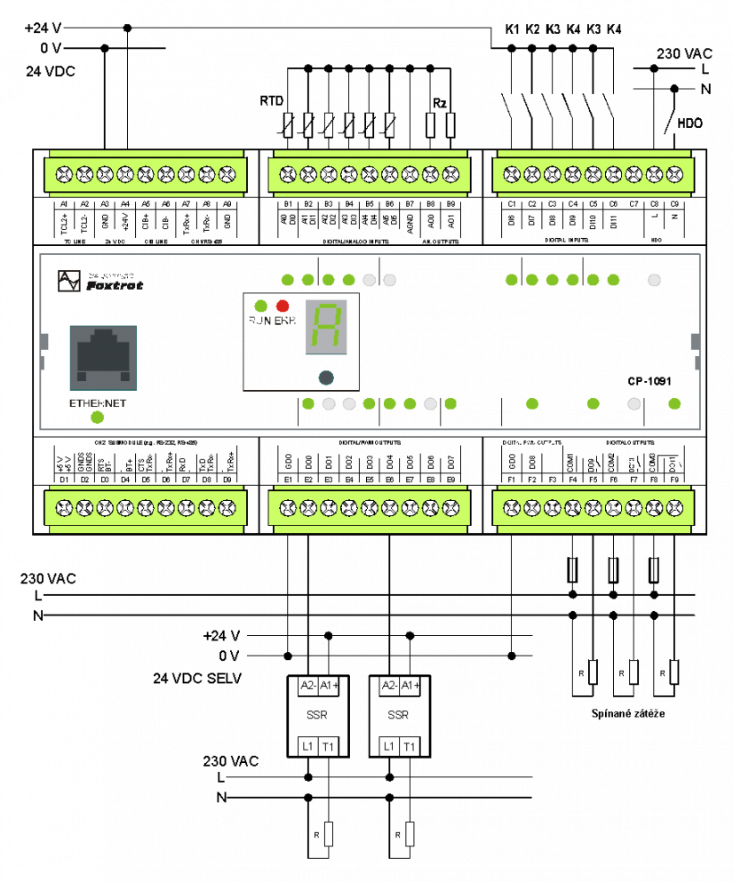
Fig. 1 A basic example of wiring the CP-1091 module and external SSR relays
Notes:
-
Identical wiring of the outputs (SSR relays) applies to DO0 up to DO8 (in the example it is only indicated in DO0 and DO4 for the sake of clarity).