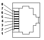
The Ethernet interface is fitted with a standard RJ-45 connector with a standard layout of signals. The connector is ready to use with common UTP patch cables (for connecting cables see Chapter 2)
Table. 1 The connection of the Ethernet interface on the basic module (front view of the PLC connector)
|
|
Pin |
Signal |
The colour of the wire |
|
8 |
not used |
brown |
|
|
7 |
not used |
white/brown |
|
|
6 |
RD– |
green |
|
|
5 |
not used |
white/blue |
|
|
4 |
not used |
blue |
|
|
3 |
RD+ |
white/brown |
|
|
2 |
TD– |
orange |
|
|
1 |
TD+ |
white/orange |

