
The output from the CH2 communication interface is located on the terminal block C or D, depending on the basic module type. The layout of signals in the terminals is available in several variants, in accordance with the basic module type:
Fig. 1 for the basic modules CP-1000 -1001 and CP-1091
Fig. 2 for the basic module CP-1003
Fig. 3 for the basic modules CP-10x4, CP-10x5.
Fig. 4 for the basic modules CP-10x6, CP-10x8.
The CH2 interface is not fitted with any submodule as a standard. The customer can choose - depending on the required interface (RS-232, RS-485, CAN, M-bus, etc.) an appropriate submodule and fit it in a free position/slot within the module (the procedure how to fit the submodule is described in the manual) TXV 004 10.
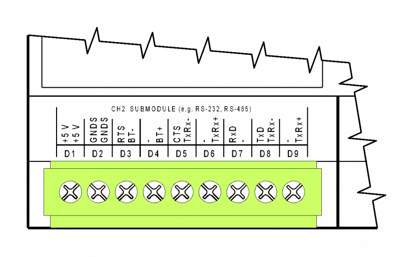
Fig. 1 The D connector of the CP-1000/1001 modules – connection of the CH2 interface, an optional interface.
Notes:
-
The descriptions on the terminals correspond to the two most common submodules - the RS-232 and the RS-485 interfaces; in other submodule variants the significance of terminals is naturally different - see the description on the specific submodule.
-
The terminal block is galvanically isolated from all circuits of the basic module. When a submodule with galvanic isolation is fitted, its inputs and outputs lead to the D connector and are galvanically isolated from other circuits of the basic module (the signal ground of the galvanically isolated interface is marked GNDS).
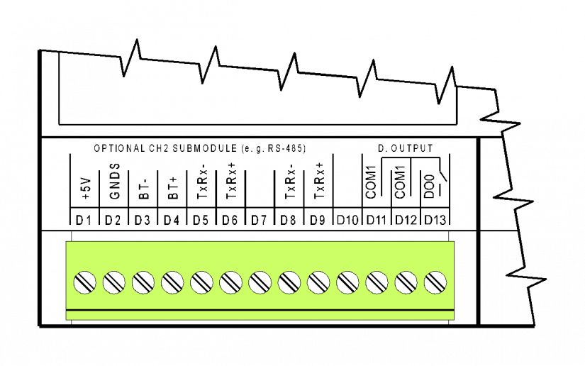
Fig. 2 The D connector of the CP-1003 modules – connection of the CH2 interface, an optional interface.
Notes:
-
The descriptions on the terminals correspond to the RS-485 interface; in other submodule variants the significance of terminals is naturally different - see the description of the specific submodule.
-
The terminal block is galvanically isolated from all circuits of the basic module. When a submodule with galvanic isolation is fitted, its inputs and outputs lead to the D connector and are galvanically isolated from other circuits of the basic module (signal ground of the galvanically isolated interface is marked GNDS).
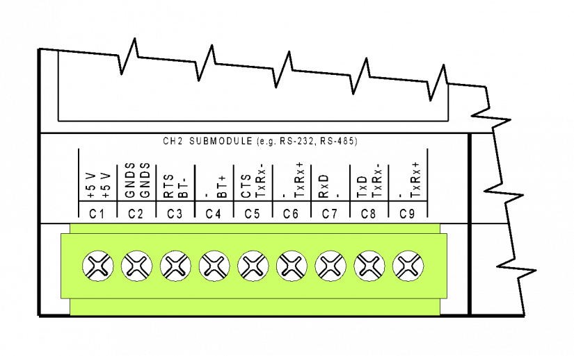
Fig. 3 The C connector of the CP-10x4, CP-10x5 modules – the connection of the CH2 interface, an optional interface.
Notes:
-
The older variants of the basic modules were fitted with fixed terminal blocks, but the numbering and the significance of all terminals is the same.
-
The descriptions on the terminals correspond to the two most common submodules - the RS-232 and the RS-485 interfaces; in other submodule variants the significance of terminals is naturally different - see the description on the specific submodule.
-
The terminal block is galvanically isolated from all circuits of the basic module. When a submodule with galvanic isolation is fitted, its inputs and outputs terminated on the C connector are galvanically isolated from other circuits of the basic module (the signal ground of the galvanically isolated interface is marked GNDS).

Fig. 4 The D connector of the CP-10x6, CP-10x8 modules – connection of the CH2 interface, an optional interface.
Notes:
-
The CH2 interface in these basic modules is only terminated on D1 to D5 terminals (the descriptions on the box again describe the signals for RS-232 and RS-485 interfaces). N.B: Some submodules have limited use, and some cannot be fitted at all in these basic modules.
-
The DO0 and DO1 outputs are terminated on D7 to D9 terminals - the SSR outputs 230 VAC, 1 A outputs are galvanically isolated from all other circuits of the basic module.
-
The terminals of the CH2 D1 up to D5 interfaces are galvanically isolated from all other circuits of the basic module. When a submodule with galvanic isolation is fitted, its inputs and outputs terminated on the C connector are galvanically isolated from other circuits of the basic module (the signal ground of the galvanically isolated interface is marked GNDS).