
The C-OR-0011M-800 module is equipped with 11 relays, separately terminated, with a switching contact. Continuous current in each output is 16 A, brief switching current up to 800 A (max. for 200 μs) – see detailed information on the relays used).). The module is in a 6M box on a DIN rail.
The module is designed to switch the capacitive (electronic power supplies for LED lamps, switching power supplies etc.) loads, socket circuits and inductive loads.
The module can be powered directly from the CIB (its power input limits the number of modules on one branch of the bus), or it can be powered from a separate 24 VDC supply (which can be used for multiple modules placed immediately next to each other); then the CIB bus is not loaded.
If you connect an external 24 V supply to the A6 terminal (or A7, as the terminals are internally connected) and A8 (or A9), the module power supply will be automatically switched to the source connected to these terminals. To switch the power supply, a higher voltage than 19.2 V must be brought to the A6 terminal.
|
External 24 VDC power supply (the A6 or A7 terminal). |
19.2 ÷ 30 VDC |
|
Maximum consumption from the 24 VDC external power supply connected to the A6 or A7 terminal. |
200 mA |
Isolation voltage:
among individual connectors and among the outputs divided at least by one free terminal (e.g. DO5, DO6, DO7) is 4,000 VAC (safe isolation of circuits),
between the outputs DO1 and DO2 the isolation voltage is 1,000 VAC.
between the outputs DO3 and DO4 the isolation voltage is 1,000 VAC.
between the outputs DO8 and DO9 the isolation voltage is 1,000 VAC.
between the outputs DO10 and DO11 the isolation voltage is 1,000 VAC.
The module is fitted with a relay with a continuous current of 16 A and terminal blocks with a maximum wire cross-section of the wire 4 mm2.
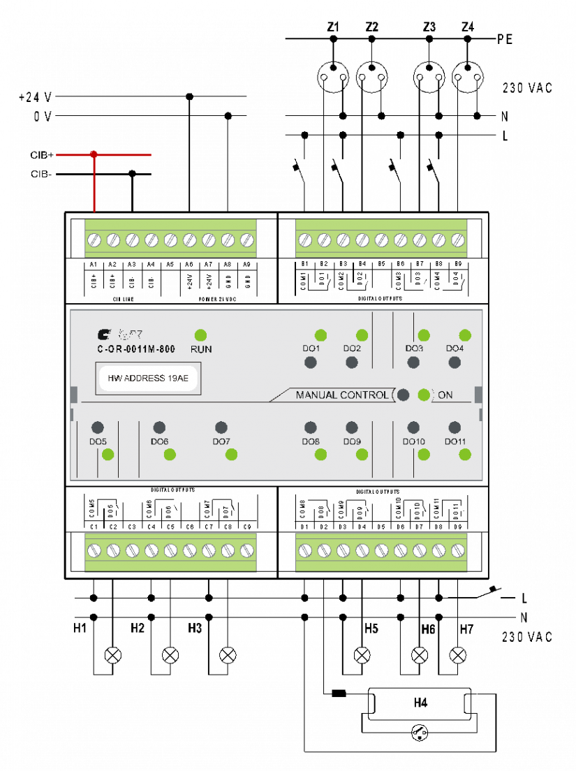
Fig. 1 The basic wiring of the C-OR-0011M-800 module