
The sensor of solar radiation (intensity), order no. TXN 134 07, uses for its measurements a monocrystalline silicon solar cell with an integrated temperature sensor; it is used for temperature compensation of the solar cell.
The module is supplied in a plastic box made of UV-resistant polycarbonate. The sensor is placed in the cap housing under the resistant cover glass. The measurement includes a temperature compensation of the intensity sensor.
The output of the measuring element and the temperature sensor is terminated by insulated strings with colour insulation with stripped and tinned ends. The length of the wires is about 100 mm.
The sensor is available either as part of a complete CIB module C-IT0200I-C-SI, or it can be installed separately and connected to the analogue inputs (measuring of the output voltage of the sensor itself and the NTC 12k temperature sensor) of the modules C-IT-0200I, C-HM-xxxxM, R-HM-xxxxM, C-AM-0600I.
The level of intensity (W/m2) is calculated using the function in the programming environment, where you need to enter the specific sensor calibration constant; it is written on the label on the internal side of the cap, and it should be copied before the sensor is mounted.
The basic parameters:
|
Measuring the intensity of solar radiation |
0 ÷ 1500 W/m2 |
|
Spectral sensitivity |
380 ÷ 110 nm |
|
The visual angle of the sensor |
179 ° |
|
Typical accuracy of the intensity sensor |
±5 %* |
|
Maximum temperature measurement error |
±2 °C |
|
The operating temperature of the sensor |
-30 ÷ +70 °C |
|
Calibration of the sensing element in STC (Standard Test Condition) |
25 °C, 1,000 W/m2, spectrum AM 1.5 |
* Calibrated by a simulation calibrator, comparison with the Kipp & Zonen CMP11 pyranometer (ISO secondary standard).
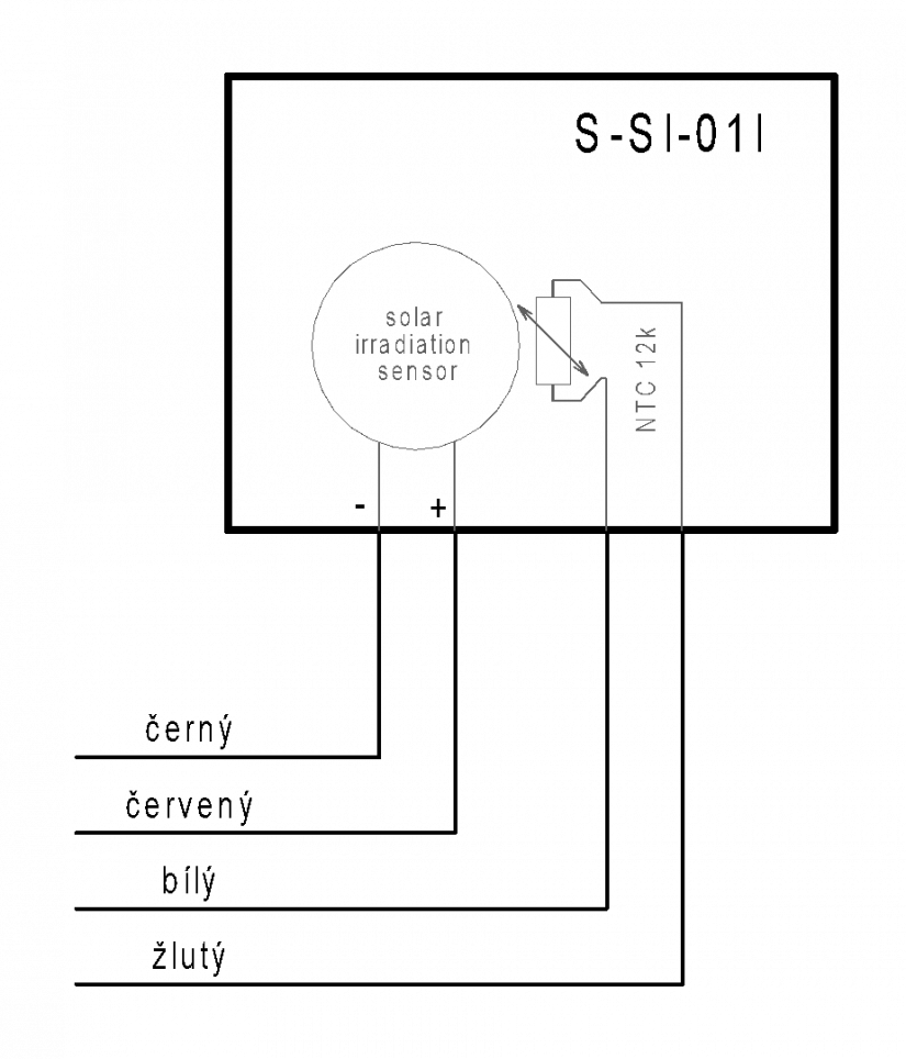
Fig. 1. Terminating the signals of the sensor of solar radiation S-SI-01I

Fig. 2. The solar radiation sensor S-SI-01I
Notes:
-
During measurements relating to the PVPS or thermal solar panels, the sensor should be placed close to the panels, and it should also be oriented in the same way, ideally with the gland downwards, see the figure.
-
Fix the module with two screws, which can be fitted after removing the module cover - see a detailed description of the box in the Chapter .
-
The sensor signals are brought out from the box from the underside of the cap in wires with colour-coded insulation; the wire tips are stripped and tinned, the length is approx. 100mm.
-
The sensor outlets can be extended as necessary, ideally with a shielded cable of 0.5 mm minimum diameter and approx. 10-20 meters maximum length. Even a longer cable can be used, but it must be shielded, correctly connected and it should not run in parallel with power lines.
-
There is a label on the underside of the cap, which contains the sensor calibration constant. It should be copied prior to the module assembly. This constant is then entered as a parameter of the function that implements the necessary calculations.