
The C-RC-0011R interior control unit with an LCD display and 5 touch buttons is designed primarily for local control of heating, cooling and ventilation systems for office buildings, such as remote control for heating systems, etc. The display is equipped with a number of symbols (see Fig. 4.), which allow you to comfortably see and easily change the basic parameters of the heating system. The module is also ready for changing the weekly time schedule, which is available in the form of a function block in the Mosaic environment, and it is compatible with the Foxtrot website and can be controlled from the application iFoxtrot, SCADA in the Reliance environment.
The control unit has five touch buttons on the display that control the functions. The module is designed as a standard peripheral on the CIB bus.
The module is further equipped with an internal temperature and humidity sensor of the interior and it is fitted with an analogue AI1 input that allows the connection of e.g. a floor temperature sensor, or an outdoor temperature sensor.
The parameters of the connectors used are listed in Chap. 13.3.1
Basic parameters of the AI1 input:
|
|
The range of measured values |
|
Pt1,000 |
-90 °C ÷ +320 °C |
|
Ni1000 |
-60 °C ÷ +200 °C |
|
NTC 12k |
-40 °C ÷ +125 °C |
|
KTY81-121 |
-55 °C ÷ +125 °C |
|
Resistance max. 100 kΩ |
0 ÷ 100 kΩ |
|
Voltage 2 V |
0 ÷ 2100 mV |
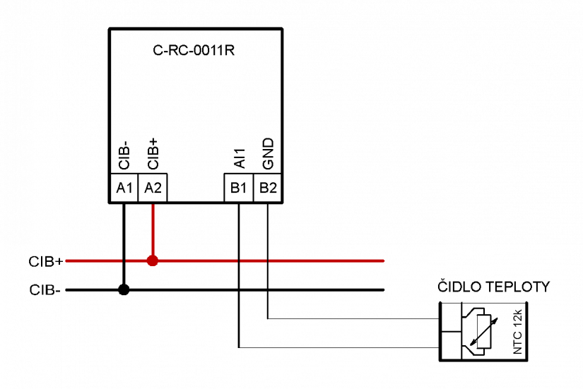
Fig. 1. A basic example of connecting the C-RC-0011R module
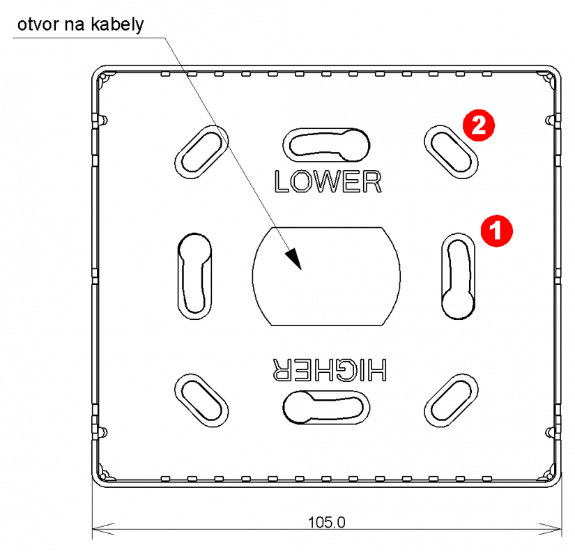
Fig. 2. Holes for mounting the C-RC-0011R module on the wall or in a flush box
Notes:
-
The support part of the control unit is mounted using the pressed holes in a standard flush box with 60 mm spacing (in the figure holes ①), or in flush boxes with the spacing used e.g.in Switzerland (in the figure the holes in the corners ②), or on a flat surface using bolts or screws. The central hole is intended for pulling through the cables to the module terminals.
-
Correct orientation of both parts must be observed during the mounting. The support part of the C-RC-0011R module must be mounted on the wall exactly as shown in the fig. - the text “LOWER” must be properly oriented. The housing with the display must again be properly mounted onto the support part. See Fig. 3., for correct orientation. The Teco logo on the inside of the housing must also be correctly oriented.

Fig. 3. The placement of the connector on the rear side of the housing of the C-RC-0011R module
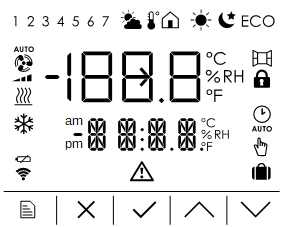
Fig. 4. A complete set of symbols on the C-RC-0011R module display
Notes:
-
The bottom row of symbols also represent capacitive buttons for operating the module.
-
The module can be operated either using the prepared function blocks, or if necessary, each symbol can be operated individually from the user program - see the module SW manual.