
The hotel control unit the C-RC-0005R is equipped with capacitive buttons (see the picture below), and an OLED display.
The buttons allow you to easily and intuitively change the required room temperature, the ventilation or air conditioning parameters, as well as allow local setting of alarms and “Do not disturb” and well as “Clean up the room” notices on the external side of the door (provided the facility allows this).
It will be possible to supply the module with customized glass - variable basic colour of the module, inscriptions, logos, etc.
The module measures the room temperature and humidity, and it is also equipped with two inputs AI/DI1 and AI/DI2 for connecting additional temperature sensors, window contacts, etc.
The module is placed in a plastic box with a glass front surface, which is pushed onto the holder bolted to the rectangular installation box (a standard flush-mounted installation box or a hollow-wall box).
The parameters of the connectors used are listed in Chap. 13.3.1
Basic parameters of the inputs:
|
The AI/DI1 ÷ AI/DI2 inputs |
The range of measured values |
|
Pt1000 |
-90 °C ÷ +320 °C |
|
Ni1000 |
-60 °C ÷ +200 °C |
|
NTC 12k |
-40 °C ÷ +125 °C |
|
KTY81-121 |
-55 °C ÷ +125 °C |
|
Maximum resistance 100 kΩ |
0 ÷ 100 kΩ |
|
Voltage 2 V |
0 ÷ 2100 mV |
|
Binary input |
Voltage-free contact |
|
Power supply and communication |
|
| Power supply and communication | 24 V (27 V) from CIB bus |
| Max current | 85 mA |
| Connection |
screw terminal block,
wire max. 1.5 mm2 |
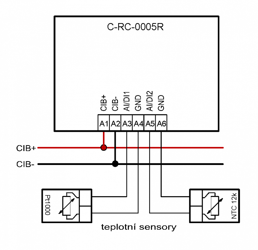
Fig. 1. A basic example of connection of the C-IR-0005R module

Fig. 2. Mounting the C-RC-0005R module holder onto the flush box; the example feature the PB503 flush box
Notes:
-
The control unit holder is mounted into the holes in a standard flush box with the 83.5 mm spacing (the screw heads are indicated in the fig.).
-
When mounting the C-RC-0005R module, make sure that you observe its correct orientation.Put the module proper with the display correctly into its holder - see Fig. 3.; the Teco logo on the inside housing must not be reversed.
-
Suitable electrical junction boxes are e.g. the BTicino 503E flush boxes (106 x 71 x 52 mm), or the BTicino hollow-wall boxes, type PB503 (106 x 71 x 52 mm).

Fig. 3. The placement of the connector on the rear side of the housing of the C-RC-0005R module
Notes:
-
The figure shows the support piece, which should be screwed onto the flush box. The display module itself should be pushed in by applying light pressure. It can be released again by pulling more strongly.