
Measuring outdoor relative humidity and temperature can be done using the C-RQ-0400I sensor.
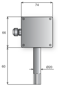
The actual temperature and humidity sensor is located in a plastic ABS stem, which is terminated with a dust filter. The electronic component, including the terminal block (CIB, 2x AI/I) is located inside the plastic head made of polycarbonate.
For an example of connection, see the Chapter Measurement of outdoor relative humidity and temperature, CFox module C-RQ-0400I.
Exposure to atmospheric conditions should be avoided by correct placement of the sensor, e.g. under the roof (the sensor is not designed for direct contact with water).
Basic parameters
|
Resolution of temperature/humidity |
0.1 °C / 0.1 %RH |
|
Maximum temperature measurement error |
± 0.5 °C (20 ÷ 40 °C), ± 1 °C (0 ÷ 60 °C) |
|
Maximum humidity measurement error |
(+25 °C) ± 3 % (20 ÷ 80 %RH) |
|
The operating temperature/relative humidity range of the sensing part |
maximum 80 °C, see the chart in the next chapter. |
|
The operating temperature range of the electronics in the head. |
-20 ÷ +60 °C |
|
The range of the storage temperature/relative humidity |
-20 ÷ +60 °C / 20 ÷ 80 %RH |
|
Ingress protection of the box / and the sensor: |
IP65 / IP40, filter 100 μm |
|
Terminal block |
|
|
The gland/max. Ø cable |
PG9/8 mm |
The properties of the temperature and relative humidity sensor
The sensor used (identical with a number of other sensors, such as the RQ-C-0400 or C-RQ-0600R) measures the temperature and relative humidity (RH). The application ranges of the sensor defined by the manufacturer are illustrated in the following chart:
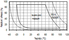
Fig. .1 A chart of the sensor operating temperature
In a normal operating range the sensor works with standard accuracy. If the sensor has been exposed to conditions outside the normal range for a long time, especially in terms of relative humidity> 80 %, the measurement error may temporarily increase up to 3 %RH. After the conditions return to the normal range, the measurement accuracy gradually returns to standard values.
Long-term exposure to extreme conditions may accelerate the ageing process of the sensor.

Fig. 2. Layout of the terminals in the C-RQ-0400I module.
Notes
-
The glands are fitted in the factory with plugs, which should be removed if necessary. The unused glands provide sufficient protection of the module.
-
The module is fitted with a screwless terminal block of the Push In type.
-
The connector in the bottom left corner should be used for connecting the combined temperature and humidity sensor.
-
The chapter with the description of the C-RQ-0400I-xx module also presents a diagram of the mechanics of the module with the glands and the terminals layout.