
The C-IT-0200I is a module on the CIB bus containing 2 analogue inputs. The inputs can be configured for measurement of resistance temperature sensors, thermocouples, resistance, voltage or current.
The module power supply (including powering the current loops 4 to 20 mA) is from the CIB. The module is in the version with a higher protection IP-65, in a box fitted with glands, the external dimensions are 125x100x38 mm.
Configuration of the measurement range is done by connecting the sensor to the relevant terminals and by setting the jumpers. Examples of connection of the terminals and configurations of the jumpers for various ranges are shown in Fig. 2.
Measurement ranges and the input resistance of the module analogue inputs.
|
Input resistance |
According to the range:
RTD, NTC, OV 0 ÷ 10 V, 0 ÷ 5 V,-2 ÷ 2 V, -1 ÷ 1 V TC, HI -1÷1 V, HI -100 mV ÷ 100 mV Current loop 0÷20 mA, 4÷20 mA |
4,7 kΩ 54,6 kΩ 4 MΩ 50 Ω |
|
Measurement ranges |
Pt1000 – W100=1,385 Pt1000 – W100=1,391 Ni1000 – W100=1,500 Ni1000 – W100=1,617 NTC12k KTY81-121 TC – type J TC – type K TC – type R TC – type S TC – type T TC – type B TC – type N Voltage input 0 ÷ 10 V Voltage input 0 ÷ 5 V Voltage input -2 ÷ 2 V Voltage input -1 ÷ 1 V Voltage input HI -1 ÷ 1 V V. in. HI -100 mV ÷ 100 mV Current loop 0 ÷ 20 mA Current loop 4 ÷ 20 mA OV 200 kΩ |
-90 °C ÷ 320 °C -90 °C ÷ 320 °C -60 °C ÷ 200 °C -60 °C ÷ 200 °C -40 °C ÷ 125 °C -55 °C ÷ 125 °C -210 °C ÷ 1200 °C -200 °C ÷ 1372 °C -50 °C ÷ 1768 °C -50 °C ÷ 1768 °C 200 °C ÷ 400 °C 250 °C ÷ 1820 °C -200 °C ÷ 1300 °C 0 mV ÷ 10000 mV 0 mV ÷ 5000 mV -2000 mV ÷ 2000 mV -1000 mV ÷ 1000 mV -1000 mV ÷ 1000 mV -100 mV ÷ 100 mV 0 mA ÷ 20 mA 4 mA ÷ 20 mA 0 kΩ ÷ 200 kΩ |
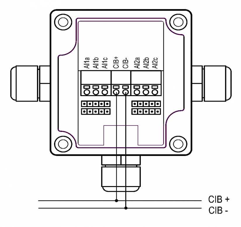
Fig. 1. Connecting the C-IT-0200I to the CIB bus, the placement of the terminal block and the jumpers.
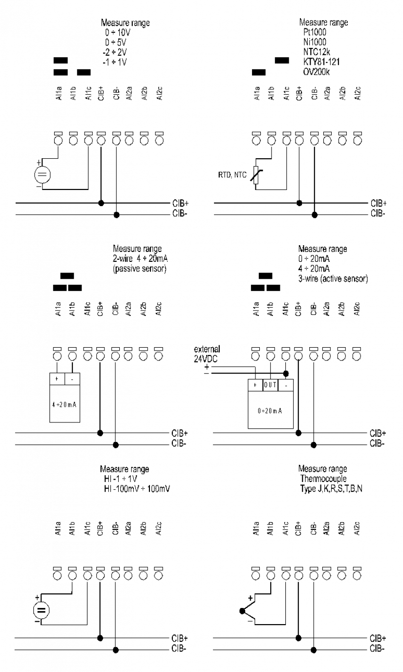
Fig. 2. Connecting the input circuit and setting the jumpers of C-IT-0200I according to the type of signal.
Notes:
-
The jumpers are always in horizontal position ( i.e. plugged in).
-
The two-wire sensor 4-20 mA is supplied from the C-IT-0200I module internal supply with the approx. 24 VDC voltage (a passive two-wire sensor); it should be connected between the a and b terminals. The externally powered sensor 0-20 mA or 4-20 mA should be connected between the b and c terminals (only a passive module input).