
The C-RI-0401S (order no TXN 133 47) is a combined module designed for a connection on the CIB bus. The module contains 2 universal analogue/binary inputs; it is possible to connect either passive resistive temperature sensors to them, or they can be used as potential-free contacts. It also includes an input for measuring illumination and includes a transmitter and a receiver of infra-red signal. The module is terminated with 10 connector pins with a counterpart, with terminated colour-coded wires with sleevings.
Compatible components of the IR transmitter and receiver are connected to the module (included in the supply), as well as a lighting sensor.
Also external temperature sensors (Pt1,000, W100=1.385) can be connected, as well as dry contacts.
Connecting elements to the wires of the module is indicated (including the colours) in the following figure.

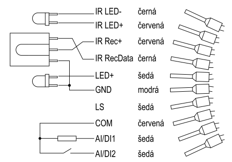
Fig. 1. Connecting the C-RI-0401S outputs (including the order and colours of the wires).
Notes:
-
IR receiver (IR Rec) and IR transmitter (IR LED) are included in the supply of the C-RI-0401S module.
-
LED (black and grey wires) is a common LED for the indication of reception of IR (the anode on LED+).
-
LS is an input of the lighting sensor (irradiance input).
-
The AI/DI1 inputs and 2 are optionally analogue (Pt1000, Ni1000, NTC) or contact inputs.
The basic parameters of inputs and outputs
IR transmitter maximum 3.3 V, 100 mA, the LED transmitter is normally a part of supply.
IR receiver a demodulator 36 kHz, it is normally a part of supply.
The lighting the BPW21 sensor, the measurement range is 0÷50,000 lx.
AI/DI AI - Pt1000, Ni1000, NTC 12k, KTY81-121, resistance up to 160 kΩ,
DI – the current excited by the input typically 3.3 mA
LED: LED indicator (controlled as a binary output).

Fig. 2. Outlets of the IR receiver TSOP31236, the IR transmitter L-7104F3C and the lighting sensors BPW21
Calculation of the external resistance for the IR transmitter
The internal resistance is 22 Ω, the external resistance is added according to the required current of the transmitting diode. The minimum recommended current is approx. 100 mA.
The connection with the L-7104F3C diode (voltage in the forward direction approx. UF = 1.2 V) and an external serial resistance R = 100 Ω (normally fitted in the C-RI-0401R-design) works with the current IF approx. 30 mA:
IF = calculation of the current IF flowing through the transmitting diode during the transmission.
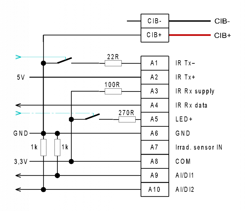
Fig. 3. Internal wiring of the C-RI-0401S module. y