
The C-RS-0200R-design is a rotary interior control unit with the one-button function with a connection to the CIB bus. At the same time it is fitted with two universal inputs terminated in the terminal block on the rear side of the module, e.g. for interconnection of the floor temperature sensors, auxiliary push-buttons (S-WS-0200R) etc.
Basic parameters of the module
|
Power supply |
from the CIB bus |
|
Power supply tolerance |
24 or 27 VDC ± 10 % |
|
The number of external inputs |
2 (DI1/AI1 and DI2/AI2) |
|
The ranges of external sensors |
voltage-free contact Pt1000: -90 °C ÷ 320 °C Ni1000: -60 °C ÷ 200 °C NTC 12k: -40 °C ÷ 125 °C KTY81-121: -55 °C ÷ 125 °C 0 ÷ 100 kΩ 0 ÷ 2 V |
|
Measurement accuracy |
± 1 °C |
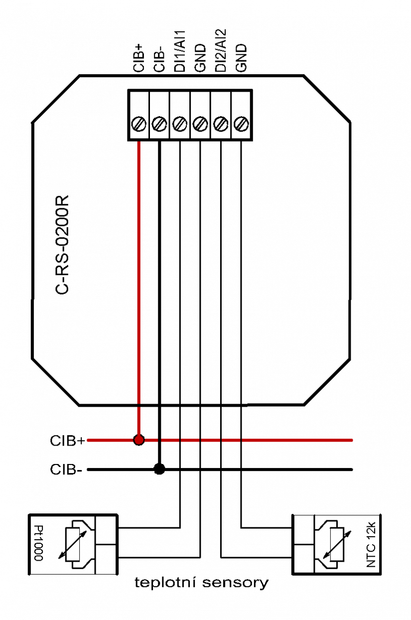
Fig. 1. An example of connecting the rotary control unit C-RS-0200R
The module is supplied in several versions for the designs: ABB, Logus and Obzor. Each variant has a given design of the rotary control shaft (for proper insertion of the control unit). The ABB design includes a clamp in its standard accessories, which secures housing with the frame to the module itself. The housing for this design also includes screws to fix the Logus and Obzor design housing and the frame.
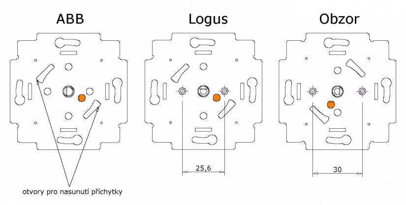
Fig. 2. The fixing holes for the C-RS-0200R module for individual designs
Notes:
-
The left image shows the holes for pushing in the clamp for fixing the housing and the frame for ABB designs. The clamp is a standard part of the C-RS-0200R-ABB module.
-
The middle figure shows the orientation of the module and the correct holes for screwing on the frame in the Logus design.
-
The figure on the right has highlighted screw holes for the housing in the Obzor design.
-
The coloured circle represents the temperature sensor in the hole in the module, that can also help you find the right orientation when mounting the module onto the flush box (assuming it is a standard type KU 68).

Fig. 3. The assembly of the C-RS-0200R rotary control unit in Logus and Obzor designs
-
The rotary control unit, a part of the housing in the selected design.
-
The dimmer housing in the selected design and colour: 90721 Txx (Logus), DSD00-2700xx (Decente), DSE00-270xx (Variant and Elegant).
-
The frame in the selected design and colour.
-
The body proper of the C-RS-0200R-Logus or C-RS-0200R-Obzor module.
Mounting of the module:
Screw the C-RS-0200R-Logus or C-RS-0200R-Obzor module onto a standard flush box (e.g. the KU 68 - part 4 in the figure).The orientation of the module according to the design is indicated in Fig. 2.
Screw the housing (part 2) onto the module; this will help you to fasten the frame (part 3) to the module. In Lotus design, use the housing of the two-way dimmer 90721 T, and a frame according to the selected colour.The Obzor designs require the dimmer housing with a rotary push-button switch DSD00-270XX for the Decente deign, or the DSE00-270XX for the Elegant and Variant designs.
As the last part of the assembly, push the rotary control (part 1) onto the module shaft; the rotary control is a part of the housing in the selected design.
Fig. 4. An assembly of the C-RS-0200R rotary control unit in the ABB version (in the figure is the Time design)
-
The rotary control, a part of the housing in the selected design.
-
The clip of the housing is a part of the package of the C-RS-0200R-ABB module.
-
The dimmer housing in the selected design and colour; here it is the Time design:3294E-A00123 xx.
-
The interjacent frame (doesn´t have to have other designs).
-
The frame according to the selected design and colour.
-
The body proper of the C-RS-0200R-ABB module.
Mounting of the module:
Screw the C-RS-0200R-ABB (part 6 in the figure) onto a standard flush box (e.g. the KU 68). The orientation of the module according to the design is indicated in Fig. 2.
Put the dimmer housing with the rotary control onto the module - the design in the example is Time 3294E-A00123 xx (part 3) together with the interjacent frame (part 4) and the frame (part 5). Fasten the housing on the module using a clip (part 2), which should be inserted into the holes in the module (see Fig. 2.), then slightly pushed and turned counter-clockwise.Now the housing with the frame is properly attached to the C-RS-0200R-ABB module.
As the last part of the assembly, push the rotary control onto the module shaft (part 1); the rotary control is a part of the housing in the selected design.