
The C-IR-0203S module is designed to connect two temperature sensors or binary signals, controlled by the power relay contact; it is fitted with two analogue outputs directly on the CIB bus.
The PT1000 or Ni1000 resistance sensors can be connected to the measurement inputs to measure temperature. Also the NTC12k sensor with a thermistor can be used, or the KTY81-121, against a common GND wire. The resistance is converted in the unit directly into the numerical value of temperature and transmitted to the central unit over the CIB. Other types of RTDs can use the resistance range from 0 to 160 kΩ, but the conversion to temperature and the linearization must be done on the programme level.
Binary signals are connected to the inputs only as free dry contacts against the common GND wire.
The analogue outputs voltage 0÷10 V is terminated on the terminal block against the common GND signal.
The output changeover relay contact is terminated in a separate terminal block, the maximum continuous output current is 3 A. The module is equipped with a relay with the maximum current of 16 A on the contact, the switching contact enables a short-term current of up to 80 A. The module is suitable e.g. for switching and control of electronic ballasts or as direct lighting control (sensing the push-buttons on the wall, and direct switching of the light sources).
The parameters of the universal inputs.
|
The input type (connected sensor) |
The range of measured values |
|
PT1000 |
-90 °C ÷ +320 °C |
|
Ni1000 |
-60 °C ÷ +200 °C |
|
NTC 12k |
-40 °C ÷ +125 °C |
|
KTY81-121 |
-55 °C ÷ +125 °C |
|
Maximum resistance 160 kΩ |
0 ÷ 160 kΩ |
|
Binary input |
Log. 0 >1.5 kΩ / log 1 <0.5 kΩ |
|
A balanced contact |
The loop resistance 2x 1k1 |
Basic parameters of the analogue outputs
|
Nominal output voltage UJM |
10 V |
|
Adjustable range of output voltage |
0 ÷ 105 % UJM |
|
Loading resistance |
>1 kΩ |
|
Maximum load capacity |
250 nF |
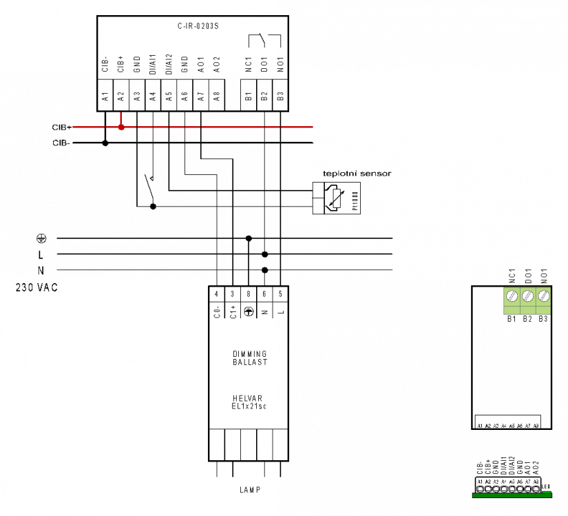
Fig. 1. An example of connecting the C-IR-0203S module and an illustration of the module terminals layout.
Notes:
-
The module inputs and outputs (except for the relay output) are terminated on a miniature terminal block.
-
The terminal block allows the release of the wire using a narrow screwdriver, or even a common pin: insert it into the hole above the space for the wire and then pull the wire.
-
The LED is next to the terminal block and it is partly hidden under the housing of the module.
-
The relay output is terminated in a separate screw terminal block; the wire cross section (a solid wire) is 0.12 mm÷ 1.5 mm2.