
The C-IR-0202S module is designed to connect two temperature sensors or binary signals, power relay contact control, and control analogue voltage directly on the CIB bus. The signals from the module are terminated by a strip conductor.
The PT1000 or Ni1000 resistance sensors can be connected to the measurement inputs to measure temperature. Also the NTC12k sensor with a thermistor can be used, or the KTY81-121, against a common GND wire. The resistance is converted in the unit directly into the numerical value of temperature and transmitted to the central unit over the CIB. Other types of RTDs can use the resistance range from 0 to 160 kΩ, but the conversion to temperature and the linearization must be done on the programme level.
Binary signals are connected to the inputs only as free contacts against the common GND wire.
The analogue output voltage from 0 to 10 V is terminated on a wire against the common GND wire.
The output relay switching contact is terminated by two separate wires with enhanced insulation.
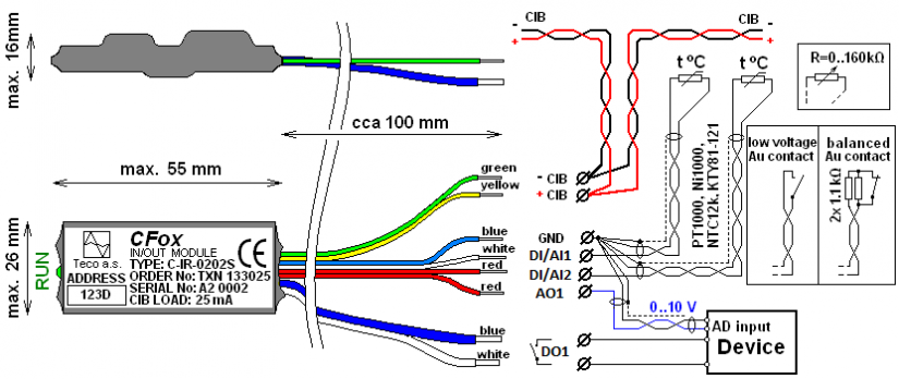
Fig. 1. The signal layout of the C-IR-0202S module, the wire colour coding and the basic connection (the old version before November 2012)
Notes:
-
The module outputs (except for the DO1 relay contact) are insulated wires with a 0.14 mm2 cross section, the length approx. 10 cm, terminated with a pressed-on sleeve H0,25/10.
-
The DO1 relay outputs are insulated wires with a 0.5 mm2 cross section, the length approx. 10 cm, terminated with pressed-on sleeves with a collar.
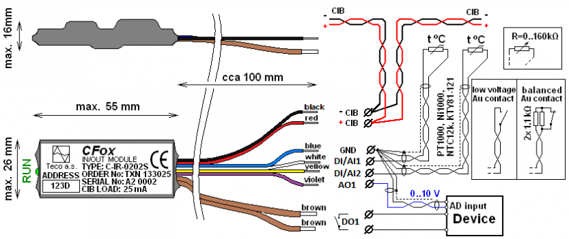
Fig. 2. The signal layout of the C-IR-0202S module, the wire colour coding and the basic connection
(the new version after November 2012)
Basic parameters of the DI/AI1 and DI/AI2 inputs
|
The input type (connected sensor) |
The range of measured values |
|
PT1000 |
-90 °C ÷ +320 °C |
|
Ni1000 |
-60 °C ÷ +200 °C |
|
NTC 12k |
-40 °C ÷ +125 °C |
|
KTY81-121 |
-55 °C ÷ +125 °C |
|
Maximum resistance 160 kΩ |
0 ÷ 160 kΩ |
|
Binary input |
Log. 0 >1.5 kΩ / log 1 <0.5 kΩ |
|
The loop resistance 2 x 1k1 |
Basic parameters of the analogue output AO1
|
Nominal output voltage UJM |
10 V |
|
Adjustable range of output voltage |
0 ÷ 130 % UJM |
|
Loading resistance |
>1 kΩ |
|
Maximum load capacity |
250 nF |

Fig. 3. Internal wiring of the C-IR-0202S module.