
The C-DM-0402M-RLC is a dimming module for the CIB bus, fitted with 4 inputs and 2 outputs. The outputs are two independently phase-controlled and managed 230 VAC channels, each for loads up to 500VA. The dimmer and its control algorithm is designed with an emphasis on reliability and immunity to interference in the network, and in particular immunity to interference by the ripple signal.
The dimmer version is RLC, i.e. it can handle both standard resistive load as well as inductive and capacitive loads. The type of load (RL or RC) is set in the software configuration and it is indicated on the front panel by LEDs:
|
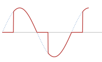
RL - an inductive and resistive load - it is switched on during the half-wave, and switches off at zero. Typically they are inductive transformers and incandescent bulbs. |
 |
|
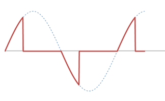
RC - a capacitive and resistive load - switching on at zero and switching off during the half-wave: These are usually electronic transformers, dimmable switching power supplies and incandescent bulbs. |
 |
LED/CFL – it lights up along with the selected type of load (i.e. it lights together with the RL or RC signalling), if there is a need to limit the dimming range and the parameter MINIMUM (light on threshold) is set on a non-zero value.
The MINIMUM parameter is used to control dimmable compact fluorescent lamps (CFL) or LED bulbs due to an inability to function from the zero output voltage - if the dimmer output is set to a smaller than recommended value of MINIMUM, they behave abnormally, flash, etc. The type of load that should usually be set for these sources is RL.
Dimming of various types of sources
Incandescent bulbs can be dimmed up to the full power input of 500 VA; a parallel operation can also be utilized up to the overall power input of 2,000 VA (see the following paragraph).
LED bulbs can be dimmed up to a total power input of 250 VA; dimming multiple LED bulbs connected in parallel is possible up to 16 pieces, but what must be taken into account are the technical parameters defined by the manufacturer (a limit for the number of simultaneously dimmed bulbs).
Compact fluorescent lamps (CFL) can be dimmed up to a total power input of 250 VA.
Inductive transformers can be used up to the 250 VA power input, provided the minimum continuous load is 80% of the transformer nominal power output.
The stated inputs are valid for the 230 VAC network. In the case of using dimmers in the 110 VAC (50 or 60 Hz) network, all power outputs and inputs are only half!
Dimming higher power
The C-DM-0402M-RLC dimmer is prepared for parallel operation of up to 4 channels, so it can dim loads up to 2 kVA (valid only for resistive loads - incandescent and halogen bulbs). It is possible to connect in parallel two channels (1 kVA output), three channels (1.5 kVA) and maximum 4 channels with a total dimmed output of 2 kVA.
The modules must always be on the same CIB branch (thus taking care of their mutual synchronization).
From the perspective of the power load, which causes warming of the modules, it is preferable to spread the load evenly among the modules; i.e. if there is 1 lamp with a 900 A power input and 2 lamps with a 60 VA power input, is would be appropriate to combine two channels of two separate dimmers for the 900 VA output (e.g. OUT1 outputs of both modules) and to use the second channel of each dimmer (OUT2) for the 60 VA load, then each C-DM-0402M RLC module would be loaded with max. 510 VA, which would significantly reduce the thermal load of each dimmer module.
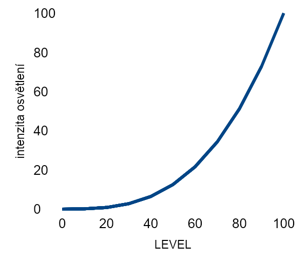
The output curve.
There are two optional characteristics implemented in the dimmer: either linear, or logarithmic dimming characteristics (see the curve in the chart on the right); the second one reflects better a great sensitivity of human sight in minimum light intensity, so the light intensity control is more pleasant for your eyes.
The front panel contains an indication of CIB bus communication labelled RUN, as well as control and indication of the manual function control. The transition to the manual mode during a standard operation of the module can be made by pressing the button, and the switching to manual mode is indicated by a yellow LED. This control can be disabled in the configuration of the module. Furthermore, each channel has a push-button on the panel, which switches the channel on in the manual mode (100% intensity) or off (0%).
The ON and ERR indication informs you about the current status of each channel, e.g. that one of the protection elements has tripped - the thermal protection or the overload protection.
The dimmer module has also 4 universal inputs AI/DI. You can connect dry contacts, resistive temperature sensors or double balanced loops with intrusion (ESS) detectors . Their functionality is enabled by the user program and it is not directly related with dimmer function.
The parameters of the AI/D inputs:
|
The input type (sensors): |
Binary, PT1000, Ni1000, NTC12k, KTY81-121, 160k, balanced inputs |
|
Binary inputs |
Log0: >1.5 kΩ, log1: <0.5 kΩ |
|
Balanced inputs |
2x 1.1 kΩ (see Chapter 13.8.4) |
|
The PT1000 input |
-90 °C ÷ +320 °C |
|
The Ni1000 input |
-60 °C ÷ +200 °C |
|
The NTC12k input |
-40 °C ÷ +125 °C |
|
The KTY81-121 input |
-55 °C ÷ +125 °C |
|
The resistance input |
0 ÷ 160 kΩ |
Synchronization of lighting scenes control
If you require synchronization of multiple independently dimmable light sources (sync-controlled lights according to pre-programmed scenes, etc.), you can use the C-DM-0402M-RLC module, which provides their automatic synchronization within one CIB branch. The synchronization ensures that the commands (the requirement for the brightness value) to all modules are executed at the same time. This only applies to one CIB branch, i.e. a maximum of 32 C-DM-0402-RLC modules.
Operating temperature and warming up of the C-DM-0402M-RLC module.
The module is heated during the operation by the heat dissipated due to the load management, which is proportional to the dimming power of both channels and the nature of dimming.
It is equipped with an internal controlled fan, which is automatically switched on if the internal temperature is increased, and provides sufficient ventilation until the maximum allowable ambient temperature of 55 °C is reached.
The module is also equipped with internal thermal protection, which reduces the output level of both channels if the temperature inside the module reaches 70 °C. This prevents thermal damage of the module and does not immediately and completely put the lighting out of operation. The thermal overload is indicated in the status of the module and it can be announced to the user, or the system can react differently. Should the temperature rise further, the module is switched off completely, and after the internal temperature decreases again, it resumes its standard function.
A stable operation of the module is ensured by defining a maximum ambient temperature, which 55 °C.
If multiple dimmers are installed together (such as lighting in larger buildings), or the ambient temperature is high, a maximum performance can be reached using additional external active cooling of the control panel, which provides controlled ventilation within the panel.
Installation of dimmers
The C-DM-0402M-RLC modules loaded by a power output approaching 500 W should be placed in the control panel in such a way, that there is enough space among them to allow ventilation (the gaps should be at least 15 mm), and the space above and below them should not be unnecessarily obstructed and impair the airflow.
It is also recommended to place the dimmers so that their dissipated heat does not effect modules with precise analogue measurement, or the basic module of the system (e.g. the CP-1000, as it is equipped with electronic thermal fuses of CIB buses, which should prevent reaching a maximum permissible current of the buses, and which could be activated by the increasing heat).
Basic parameters
|
The power loss of the module at the maximum load of 2 x 500 VA. |
maximum 2 x 4.5 W |
|
Maximum load (resistive load) 1) 2) 3) |
2 x 500 VA |
|
Minimum load |
0 VA |
|
Internal protection |
electronic fuse thermal fuse 105 °C |
|
Consumption form the CIB bus |
maximum 35 mA |
|
Operating ambient temperature |
- 20 °C ÷ 55 °C |
|
The protection class of the electrical device |
II |
1) Inductive transformers can be used up to the 250 (125) VA power input, provided the minimum continuous load is 80% of the transformer nominal power output.
2) When LED bulbs or electronic ballasts are used, the maximum load can reach only 250 (125) VA; do not connect the channels in parallel.
3) A parallel connection of module channels is only possible for a resistive load (incandescent lamps) up to the power output of 2(1)kW; the modules must be on the same CIB line. If manual control of outputs and inputs is applied, the remaining active outputs can be overloaded.