
An example of connection and the conditions of the module usage:
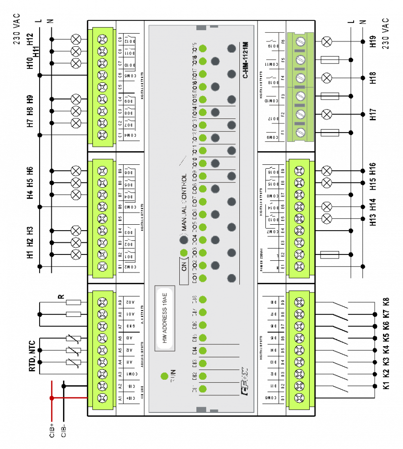
Fig. 1 The basic connection of the C-HM-1121M module
Notes:
-
The DI1 to DI8 inputs are intended only for connecting potential free contacts. The voltage on the COM2 common terminal opposite the GND terminal (analogically also CIB-) is +10 V, and the DI inputs with the switched contacts are connected to this reference voltage. When the input is excited, typically 1.5mA current flows through the contact.
-
The analogue inputs AI1 to AI3 are intended for connecting the temperature sensors and condensation sensors. The actual sensor should be connected between the input AI and the reference terminal COM1. The COM1 terminal has the +2.5 V reference voltage terminated (opposite the GND terminal).
-
The relay outputs are categorized into groups. Maximum currents and isolating voltages are listed in the following description:
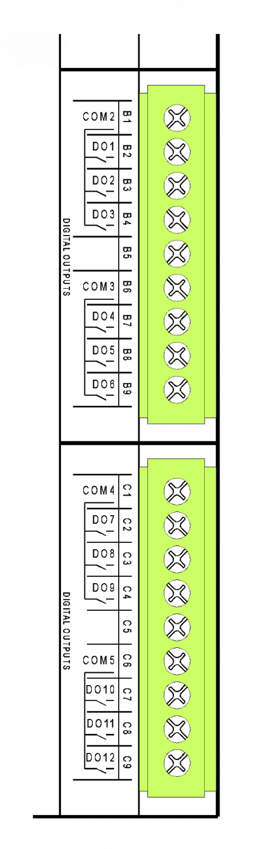
The relay outputs of the C-HM-1121M module:
Connectors B and C
|
The DO1÷DO3, outputs with a common terminal, continuous current in the 3 A output, inrush current 5 A, maximum continuous current on the common terminal COM2 is 10 A, |
 |
|
isolation voltage from the other circuits and outputs is 3,750 VAC, i.e. safe isolation of circuits. |
|
|
The DO4÷DO6, outputs with a common terminal, continuous current in the 3 A output, inrush current 5 A, maximum continuous current on the common terminal COM3 is 10 A, |
|
|
isolation voltage from the other circuits and outputs is 3,750 VAC, i.e. safe isolation of circuits. |
|
|
The DO7÷DO9, outputs with a common terminal, continuous current in the 3 A output, inrush current 5 A, maximum continuous current on the common terminal COM4 is 10 A, |
|
|
isolation voltage from the other circuits and outputs is 3,750 VAC, i.e. safe isolation of circuits. |
|
|
The DO10÷DO12, outputs with a common terminal, continuous current in the 3 A output, inrush current 5 A, maximum continuous current on the common terminal COM5 is 10 A, |
|
|
isolation voltage from the other circuits and outputs is 3,750 VAC, i.e. safe isolation of circuits. |
The E connector and F terminal block
| supply terminals of the module, supply voltage is 230 VAC | 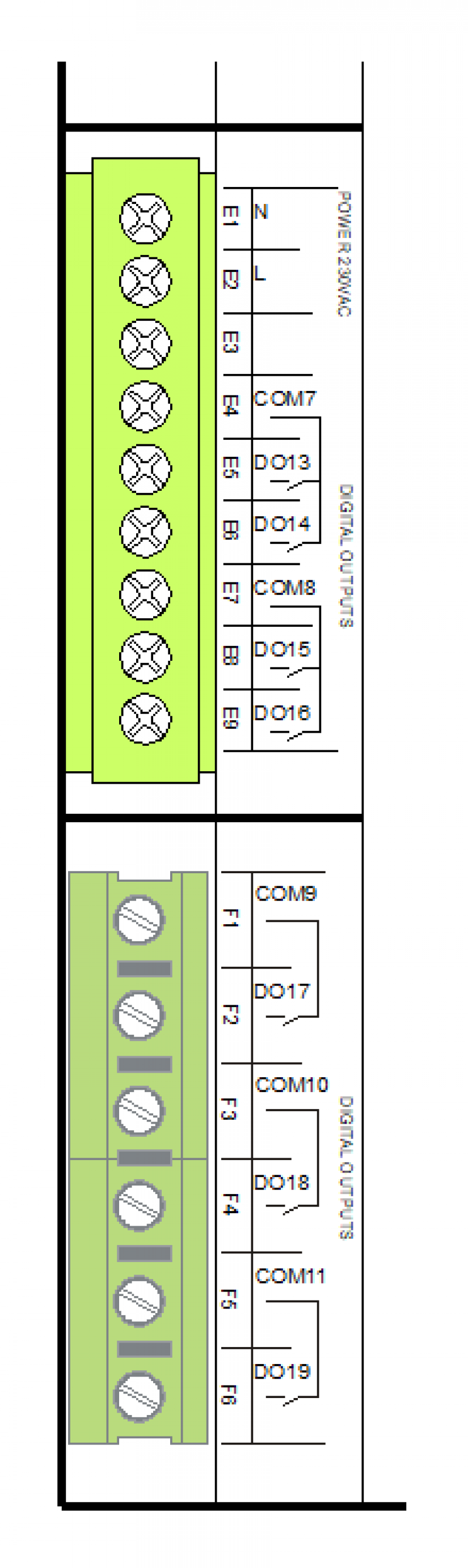 |
|
isolating voltage from other circuits and outputs is 3,000 VAC, i.e. safe isolation of circuits. |
|
|
The DO13, DO14, outputs with a common terminal continuous current in the 3 A output, inrush current 5 A, maximum continuous current on the common terminal COM7 is 10 A |
|
| There is only 1750 VAC working isolation among these groups | |
|
The DO15, DO16, outputs with a common terminal continuous current in the 3 A output, inrush current 5 A, maximum continuous current on the common terminal COM8 is 10 A |
|
|
isolation voltage from the other circuits and outputs is 3,750 VAC, i.e. safe isolation of circuits. |
|
|
The DO17, a separate output, switching contact, continuous output current 16 A (also the load DC13, AC15), short-term overloading 160 A (max. 10 ms) |
|
|
isolation voltage from the other circuits and outputs is 3,750 VAC, i.e. safe isolation of circuits. |
|
|
The DO18, a separate output, switching contact, continuous output current 16 A (also the load DC13, AC15), short-term overloading 160 A (max. 10 ms) |
|
|
isolation voltage from the other circuits and outputs is 3,750 VAC, i.e. safe isolation of circuits. |
|
|
The DO19, a separate output, switching contact, continuous output current 16 A (also the load DC13, AC15), short-term overloading 160 A (max. 10ms) |
Except for the output groups DO13, DO14 and DO15, DO16 (which are isolated only by working isolation), individual groups of outputs can arbitrarily switch low voltage circuits (even different phases) and the circuits of small safe voltage. Only groups DO13, DO14 and DO15, DO16 must be powered from a single phase, and both must be used either for circuits of small safe voltage, or low voltage in the same phase.
The relay contacts under full load have a lifetime of approx. 100,000 operations, and the maximum number of operations per minute is 20 (DO17 DO18 DO19 only 6 operations per minute). This must be taken into consideration when using relay outputs. .
More detailed information on the contacts of relays DO13 to DO16.
The parameters of the connectors used (except for the terminal block F) are stated in Chap. 13.3.1
The parameters of the F terminal block are stated in Chap. 13.3.2
The module is in a 9M box.
The parameters of the analogue inputs and outputs (including their internal wiring) are consistent with the C-HM-1113M module (see the previous chapter).