
If there is a risk of overvoltage (parallel cabling), it is recommended to increase the resilience of the systems by using the surge protection (SPD) with each connected system. In cases of outdoor cabling, the SPD should always be used!
Always use surge protection equivalent to the level of signals in the cable; you should always protect all signal conductors in the cable. The surge protection earth terminal should be always properly connected to the protective earth in the control panel (close to the supply from the grid); if several protection elements are used for different signals, all their ground terminals should be unified in one point).
Recommended SPDs manufactured by SALTEK:
The protection recommended for the RS-485 interface:
The BDM-006 V/1 R1 on a DIN 35 rail mounting (manufactured by SALTEK)
The BDM-006 V/1 R1 on a DIN 35 rail mounting (manufactured by SALTEK)
The protection recommended for the RS-232 interface:
2x the BDM-012 V/1 R1 on a DIN 35 rail mounting (manufactured by SALTEK)
The DM-012 V/2 R1 on a DIN 35 rail mounting (manufactured by SALTEK)
BDM is a comprehensive range of surge protection devices designed for protection of data, communication, measuring and control lines against surge effects. They are recommended for use on interfaces of protection zones ZBO 0A(B)-1 in accordance with the ČSN EN 62305 standard. All types provide effective protection of the connected equipment against transverse and longitudinal surges in accordance with the IEC 61643-21 standard. Nominal operating current of individual protected lines IL < 1 A.
The 1st degree is designed using three-pole arresters, 2nd degree using transils. The number of protected pairs is optional (1 to 2). They are designed for the nominal operating voltages from 6 V to 170 V. For this type, the maximum leakage current is 10 kA (8/20).
Recommended SPDs manufactured by HAKEL:
The protection recommended for the RS-485 interface:
DTE 1/6-L the version on the TS35 rail (produced by HAKEL)
DTB 1/6 the version in a plastic box (produced by HAKEL)
The protection recommended for the RS-232 interface:
DTE 2/12 the version on the TS35 rail (produced by HAKEL)
DTB 2/12 the version in a plastic box (produced by HAKEL)
These types of protection are available in the basic version with a maximum discharge current of 10-kA (e.g. DTE 1/6), or in a strengthened version (with the letter L added, e.g. DTE 1/6-L) with a maximum discharge current of 20kA (for more vulnerable installations).
DTE is a comprehensive range of surge protection devices designed for protection of data, communication, measuring and control lines against surge effects. They are recommended for use on interfaces of protection zones ZBO 0A(B)-1 in accordance with the ČSN EN 62305 standard. All types provide effective protection of the connected equipment against transverse and longitudinal surges in accordance with the IEC 61643-21 standard. Nominal operating current of individual protected lines IN < 0.1 A.
The 1st degree is designed using three-pole arresters, 2nd degree uses transils. The number of protected pairs is optional (1 to 2). They are designed for the nominal operating voltages from 6 V to 170 V. For this type, the maximum leakage current is 10 kA (8/20).
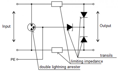
Fig. 1. Internal connection of the DTE surge protection
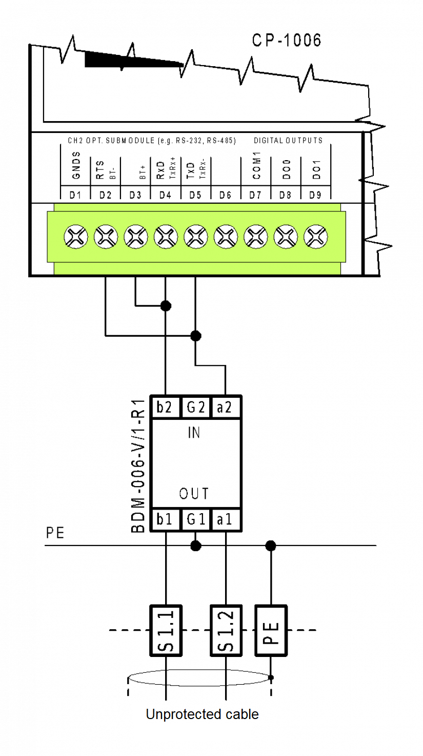
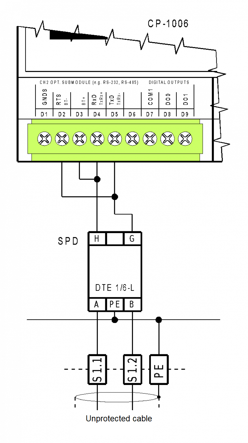
Fig. 2. An example of connecting surge protection of the RS-485 communication interface in CP-1006
Tab. 1. Technical parameters of SPDs BDM-006, BDM-012 and DM-006, DM-012 (SALTEK)
|
SPD |
|
BDM-006-V/1-R1 |
DM-006-V/1-R1 |
BDM-012-V/1-R1 |
DM-012-V/2-R1 |
|
The number of pairs |
|
1 |
1 |
1 |
2 |
|
The placement of SPD |
|
ST 1+2+3 |
ST 2+3 |
ST 1+2+3 |
ST 2+3 |
|
Nominal operating voltage |
UN |
6 VDC |
6 VDC |
12 VDC |
12 VDC |
|
The highest continuous operating voltage |
UC |
8.5 VDC |
8.5 VDC |
15 VDC |
16 VDC |
|
The rated loading current (at 25 °C) |
IL |
1 A |
1 A |
1 A |
1 A |
|
D1 total discharge current (10/350 µs) strands-PE |
ITotal |
5 kA |
- |
5 kA |
- |
|
C2 rated discharge current (8/20 µs) per wire |
In |
10 kA |
10 kA |
10 kA |
10 kA |
|
C2 protective voltage level in the wire-wire mode with In |
UP |
25 V |
- |
40 V |
- |
|
C3 voltage protection level in the wire-wire mode with 1kV/µs |
UP |
12V |
12V |
22V |
22V |
|
Response time |
tA |
1 ns |
1 ns |
1 ns |
1 ns |
|
Boundary frequency wire-wire |
f |
0.8 Mhz |
0.8 Mhz |
2 Mhz |
2 Mhz |
|
Serial resistance on the wire |
R |
0.8Ω |
0.8 Ω |
0.8 Ω |
0.8 Ω |
|
Operating temperature |
|
-40 °C ÷ +70 °C |
|||
|
Level of protection |
|
IP 20 |
|||
|
The cross-section of connected wires (solid) - max. |
|
0.14 ÷ 4 mm2 |
|||
|
The cross-section of connected (stranded) - max. |
|
0.14 ÷ 2.5 mm2 |
|||
Tab. 2. Technical parameters of SPD DTE 1/6-L (HAKEL)
|
The number of pairs |
|
1 |
|
Nominal operating voltage |
UN |
6 V |
|
Maximum continuous operating voltage |
UC |
7.2 V |
|
Nominal current |
IN |
100 mA |
|
D1 Lightning cumulative current (10/350) |
Iimp |
5 kA |
|
D1 Lightning (10/350) line/PE |
Iimp |
2.5 kA |
|
C2 Maximum discharge current (8/20) |
Imax |
20 kA |
|
C2 Nominal discharge current (8/20) |
In |
1 kA |
|
C2 Voltage protection level at In |
UP |
15 V |
|
C2 Voltage protection level at 1kV/μs |
UP |
9 V |
|
Response time |
tA |
< 30 ns |
|
Data transfer rate |
|
1 MBit/s |
|
Insertion impedance |
|
1.5 ÷ 10 Ω |
|
Parasitic capacitance |
C |
1,5 nF |
|
Operating temperature |
|
-40 °C ÷ +80 °C |
|
Level of protection |
|
IP 20 |
|
Recommended cross-section of the connected wires |
|
0.25 - 1.5 mm2 |
|
Maximum torque of the terminals |
|
0.4 Nm |
|
Tested in accordance with the IEC 61643:21-2000 standard. |
|
A2, B2, C2, C3, D1 |