
The following figure shows an example of connecting a three-command switching element to the CP-1000 module, which has information on the validity of the low tariff; the power control of the blocked appliances can also be provided directly by contractors.
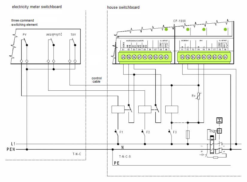
Fig. 1. Connecting a three-command switching element to the CP-1000 module
Notes:
-
The figure shows the TN-C network in the electricity meter control panel changed to TN-CS in the house control panel. In the distribution territory of ČEZ Distribuce the network can already be changed in the electricity meter control panel. In such a case the bifurcation of the PEN wire into N and PE should be drawn in the electricity meter control panel. In the distribution territory of E.ON Distribuce is also used the TT network. In this case, the N conductor and PE are completely isolated, and the PE starts with changed in the electricity meter control panel. The listed changes do not alter in any way in the illustrated sense of control by the N wire, nor in the surge protection.
-
The SP signal is usually brought by the CYKY cable from the electricity meter control panel. Usually only the blue wire is used from the cable, and the other wires should be re-marked blue (the switching element signal controls N).
-
The ripple control input in the module (the F4 and F5 terminals) is specifically designed for 230 V (it is a 230 VAC binary input), with the resistance of up to 400 VAC, and it is supplemented with a varistor, which protects the ripple control input against surges resulting from the disconnecting of the switching element signal on the contractor coil and in co-action with the assumed surge protection of the inlet against induced overvoltage of the control wire.
-
For a selection of appropriate protective elements and a table with recommended types, see the Chapter on Interference suppression, application of suppression measures.
-
Contactors or relays of all commands must be supplied from the same phase (the figure shows a one-phase network, but the usage of three-phase networks must be assumed), otherwise there would appear phase-to-phase voltage on the terminals (downstream from the coils), which means it would also appear in the ripple control of CP input, and the recommended varistor would react.
-
Other commands are scanned via auxiliary relays, whose contacts are connected to standard binary inputs of the Foxtrot system (in this case directly the CP-1000 inputs, but any binary system input can be used).
-
The phase fuse of the F5 terminal protects a disconnection of the circuit in the case of the varistor failure; it also protects the phase wire against a potential short circuits, e.g. if the Foxtrot is located in a separate control panel, and not in the house control panel.
-
If there is a protective switch installed at the supply point, the 230 V CP inputs must be connected upstream to avoid the generation of a false residual current.