
The following example shows a direct connection of two-command switching element to the CP-1000 basic module, whose power controls the blocked appliances and which also has information about the validity of the low tariff. The connection covers most switching element options, enabling Foxtrot to control also the blocked appliances.
The basic modules CP-1000, CP-10x6, CP-10x8 are equipped with a direct ripple control input, which is designed for a direct connection of the switching element (located in the electricity meter control panel) signal. As the control is implemented by the N signal, the L terminal (in the figure it is the F5 terminal) is permanently connected to the phase wire (L).
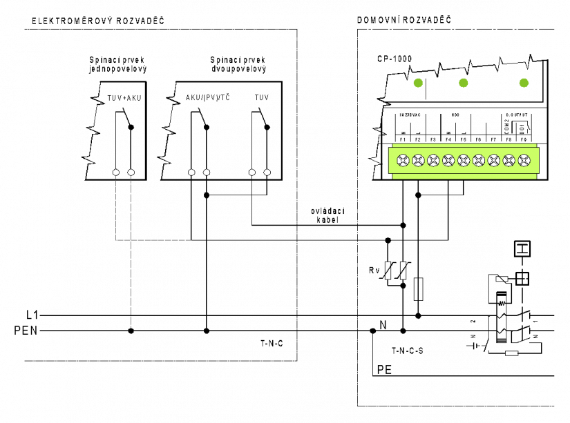
Fig. 1. Direct connection of a two-command switching element to the CP-1000 module
Notes:
-
The figure shows the TN-C network in the electricity meter control panel changed to TN-CS in the house control panel. In the distribution territory of ČEZ Distribuce the network can already be changed in the electricity meter control panel. In such a case the bifurcation of the PEN wire into N and PE should be drawn in the electricity meter control panel. In the distribution territory of E.ON Distribuce is also used the TT network. In this case, the N conductor and PE are completely isolated, and the PE starts with changed in the electricity meter control panel. The listed changes do not alter in any way in the illustrated sense of control by the N wire, nor in the surge protection.
-
There is also suggested an alternative use of one-command switching element (e.g. only in heating water, or heating water + accumulation heating up to the limit power input). Even when a one-command switching element is used, the installation in the house control panel should be prepared to simply switch to the two-command system, as the distribution tariffs or the technical specifications may be changed, etc.
-
The SP signal is usually brought by the CYKY cable from the electricity meter control panel. Usually only the blue wire is used from the cable, or in multiple-command systems another wire should be re-marked blue (the switching element is controlled by the signal from N).
-
The ripple control input in the module (the F4 and F5 terminals) is specifically designed for 230 V (i.e. it is a binary 230 VAC input).
-
The example also illustrates the connection of the second 230 VAC input (the F1 and F2 terminals), which is usually used to monitor the presence of 230VAC supply voltage (if the system has a battery backup). If necessary, this input can be used as a second ripple control input (only the CP-1000 basic module). If there is a need to monitor the supply voltage, it may be better to leave the 230 VAC input to its purpose (with the stated over-voltage problem in mind); an auxiliary relay then can be used for the second switching element command. Its contacts will control the CP digital inputs (see the following chapter).
-
If a third command of the SP should be captured, it is possible to add another auxiliary relay.
-
In cases where there is a risk of surge penetration into the control wires, it is recommended to include an SPD element. When the electric meter control panel is on the boundary of the property (LPZ 0), the control cable tends to run parallel with the power cable. If the protection is designed like this, co-action with the inlet protection is expected. For a selection of appropriate protective elements and a table with recommended types, see the Chapter on Interference suppression, application of suppression measures.
-
The phase fuse of the F2 and F5 terminals protects longer installation of the phase wire against possible short circuits, e.g. if the Foxtrot is located in a separate cabinet and not in the house control panel.
-
If there is a protective switch installed at the supply point, the 230 V CP inputs must be connected upstream to avoid the generation of a false residual current.