
The valve designed to control the distribution of drinking water (e.g. the main water valve), automatic control of irrigation systems, etc. Its design is also suitable for the so-called hard water. It is a good replacement of solenoids and pneumatic valves. The valve has a high torque and it is suitable both for drinking and contaminated water (with no solid particles). The valve is designed as a ball valve, which is used for opening and closing by an electric motor drive. The valve draws current only during its operation. During its operation, the valve consumes power from almost zero to approx. 5.5 mA, and it is recommended to switch off the supply after its position has been changed. During a power failure the valve remains in its current position and it cannot be adjusted manually. Emergency manual adjustment is possible with the version of the valve, which is equipped with a controller for manual operation (the CWC-25-06-M).
|
Name |
CWX-15-06 |
CWX-15-24 |
CWX-25-06 |
CWX-25-24 |
|
Clearance |
DN15 |
DN25 |
||
|
The screw fitting |
G1/2" |
G1" |
||
|
Nominal voltage |
3 ÷ 6 VDC |
9 ÷24 VDC |
3 ÷ 6 VDC |
9 ÷24 VDC |
|
Operating current |
typically 80 mA |
typ. 26 mA |
typ. 80 mA |
typ. 85 mA |
|
Duration of a cycle |
approx. 3 s at 3 V supply |
cca 3.5 s |
cca 3.5 s |
cca 3.5 s |
|
Operating pressure |
0.8 MPa (8 bar) |
0.8 MPa |
0.8 MPa |
0.8 MPa |
|
Output torque |
1.5Nm |
|||
|
The temperature of the medium |
0 ÷ 95 °C |
|||
|
The range of the ball valve |
90° |
|||
|
Operating medium |
water, air, gas |
|||
|
Protection |
IP65 |
|||
|
Lifetime |
100,000 cycles |
|||
|
Assembly position |
free |
|||
|
Material: |
|
|||
|
Body |
stainless steel (or brass) |
|||
|
Spherical valve |
stainless steel |
|||
|
Housing of the electronic part |
ABS |
|||
|
Sealing |
PTFE and a silicone o-ring |
|||
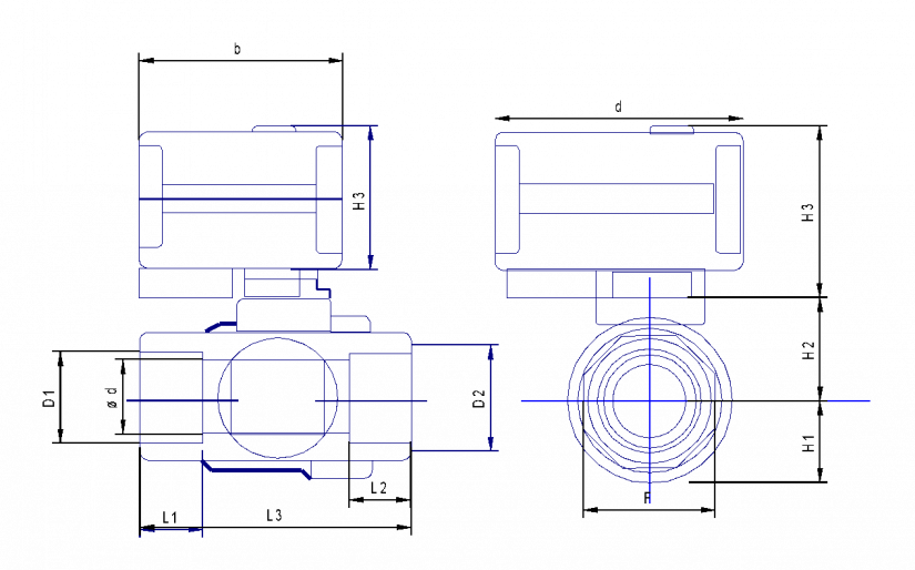
Fig. 1. Mechanical dimensions of the CWX valves.
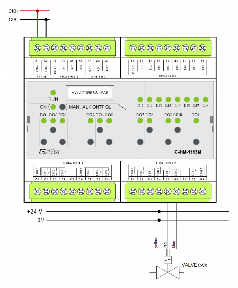
Fig. 2. Basic wiring of the CWX valve to the C-HM-1113M module
Notes:
-
The valve control is terminated in the cable with coloured insulated conductors with a tinned tip. The yellow wire represents the common terminal, the red wire voltage opens the valve (the DO9 output in the example), the blue wire voltage closes the valve (the DO10 close relay in the example).
-
N.B.: Both relays must not be switched at the same time - the valve could be destroyed. The valve is controlled in the same way as e.g. the blinds, and it is also possible to use the same output connections with mechanical interlocking switches of the two outputs, or a specialized module C-JC-0006M.