
The M-Bus is designed for connecting heat meters and similar meters that can be powered from the bus and whose data can be read remotely.
The physical layer is defined by the EN 1434 (ČSN EN 1434) standard, the data link layer is defined by the IEC 870 standard and the application layer by the CEN TC 176 standard.
The bus is implemented by two wires, which can provide powering for the meters and along which the communication runs. The meters are connected in parallel on the bus; in most cases the polarity of connections is irrelevant (see the connection requirements in the manufacturer's documentation of the meters used), there is a bus topology, with the bus length up to 4 km; a maximum number of meters connected to the bus is 250 (each meter its own unique network address). Maximum communication speed is 38,400 Bd (with limited length of the cable and the number of connected meters).
Open-circuit voltage on the bus is 36 VDC. Master (in this case it is the SX-1181 module) transmits data by varying the voltage 36/24 VDC Slave (the heat meter) responds by changing the current consumption to 1.5/20 mA (at rest it draws in accordance with the standard 1.5mA).
Voltage and current curves on the bus are shown in Fig. .1. The logic levels are identified as Mark and Space.
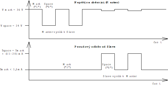
Fig. 1. The M-Bus
The “M-Bus Usergroup” standards and recommendations divide the modules providing the conversion on M-Bus interface into several categories.
The SX-1181 module corresponds with the medium variant of transducers, it is mounted on a DIN rail and it is usually connected to the CH1 of the Foxtrot basic modules fitted with the RS-232 interface.
There is also available the MR-0158 submodule, which is designed for only a small number of meters and it should be mounted in the CH2 position of the Foxtrot basic modules.