
The speed of wind (e.g. for controlling outdoor blinds and awnings - protection against strong wind) can be measured by a number of anemometers with a pulse output, which is further processed like other pulse meters (the flowmeter, etc.). You need to know the anemometer constant (the number of pulses/wind speed), which should be entered into the FB in Mosaic, and what you get is the current wind speed and other meteorological variables (maxima, minima, etc.).
The direction of wind can be measured by indicators of wind direction, equipped with a resistance output; then the indicator output signal is measured with the analogue system input.
The signal can be processed by a FB to Mosaic, which we will then recalculate the indicator resistance value to obtain the current wind direction.
The T114 anemometer and the T115 wind direction indicator have standard function blocks available, so there is no need to feed any other data in the system.
The T114 anemometer
is a standard vane anemometer, the two-wire output cable with a terminated contact output is approx. 40cm long, with an RJ connector. The anemometer is mounted behind a cylindrical mandrel with a diameter of about 18.5mm and the length 19mm.
It can be used separately or in conjunction with a wind direction indicator - then it is recommended to buy the complete set that includes an anemometer, a wind indicator and a rain gauge, as well as the basic mechanical parts for installation of sensors; see the following figure. If you install the anemometer together with the wind direction indicator, use a common holder for both sensors; it includes a vertical tube with the diameter of 20mm, which should be anchored to a suitable construction. The RJ connector of the anemometer should then be inserted in the prepared connector on the bottom side of the wind direction indicator; its cable can be used for both signals - see the wind direction indicator.
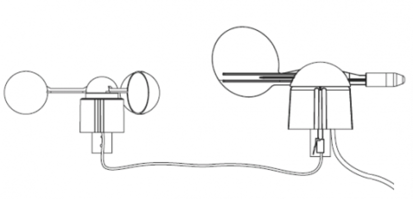
Fig. 1. Connection of the anemometer and the wind direction indicator
The wind direction indicator T115
can be used separately or in conjunction with an anemometer. It can be mounted using a mandrel with approx. 18.5 mm diameter and 37 mm length. The output signal of the wind direction and the anemometer output (if it is connected) are terminated in a four-wire 2.6 m long cable with an RJ connector.
The cable from the wind direction indicator - terminating signals:
internal wires (red and yellow) – the anemometer (a pulse output)
external wires (green and black) – the wind direction indicator (variable resistance)
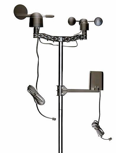
Fig. 2. The assembly with the T114 anemometer, the T115 wind direction indicator, and the T116 rain gauge
Basic parameters of the wind direction indicator T115
|
The measurement range |
from 0 ° to 360 ° |
|
The wind rose |
8 positions |
|
The resistance value |
1 ÷ 120 kΩ |
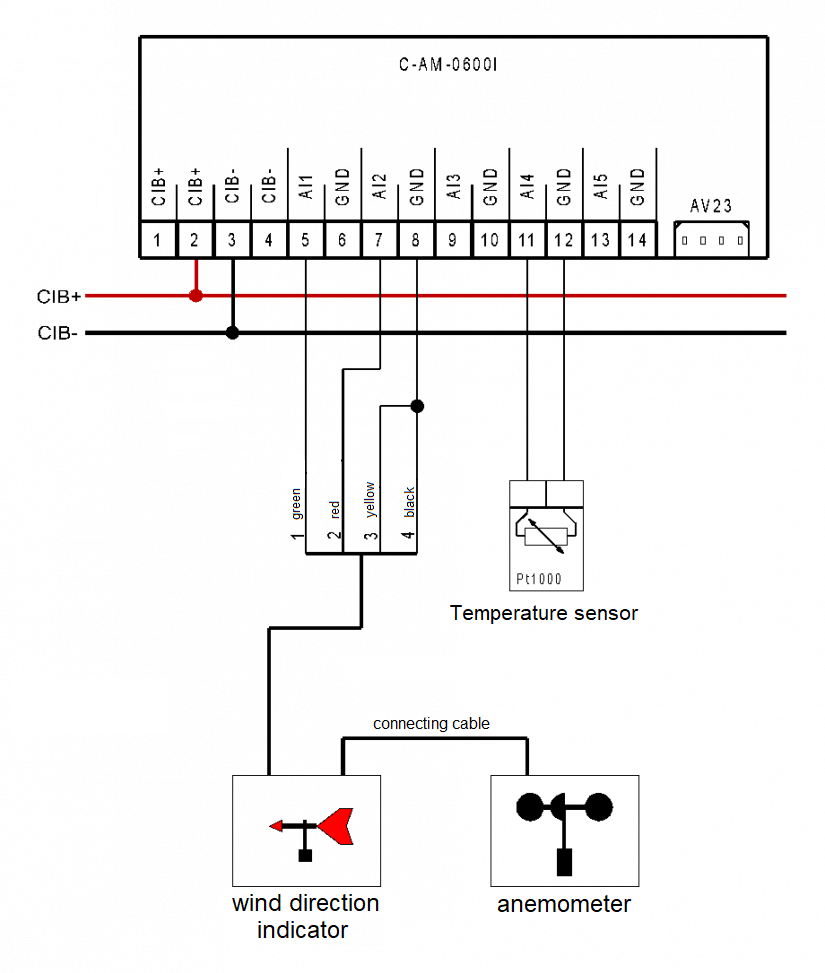
Fig. 3. An example of connection of the T114 anemometer with the T115 wind direction indicator T115
Notes:
-
The output cable from the anemometer and the wind direction indicator may be extended up to approx. 20 m.
-
The RJ connectors at the termination of the cable are not really necessary and can be removed.
-
When the C-AM-0600I module is used (as in this example), its other inputs can also be utilized, e.g. for measuring the temperature of solar panels, the outdoor temperature, etc.
-
Other accessories, such as the tipping bucket rain gauge (measuring instruments with a pulse output), are connected in the same way as the anemometer.