
The outdoor lighting is measured by the C-RI-0401S module, whose built-in version is placed in the flush box; it is terminated with a connector, to which the BPW21 lighting sensor itself should be connected (it has to be ordered separately).
The lighting sensor must be mechanically fastened in such a way, that its front part monitors the lighting and the rest of the housing is protected from mechanical impacts and the weather conditions. The positive (+) terminal of the lighting sensor (see the dimensions of the sensor in the figure) should be connected to the pin 7 (grey), and the negative pole to the pin 6 (blue).
During the handling with the sensor and the installation, caution is necessary, as this is an electronic component with fine outlets (the pins must not be bent close to the housing due to the risk of breaking).
A more detailed description of the C-RI-0401S module, including inputs and outputs connection, can be found at the end of this manual in the description of the C-RI-0401S module.
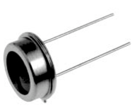
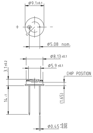
Fig. .1 The dimensions of the lighting sensor BPW21, including the polarity of the outlets.
Notes:
-
The sensor terminals (pins) must not be bent close to the housing; the sensor must be handled with care.
-
Regarding the inlet cable from the sensor to the module, it is recommended to use a shielded cable, e.g. the SYKFY 2x2x0.5, which can be extended to max. 2 m.
-
During the installation of the BPW21 sensor, and subsequently the C-RI-0401S module, you must take into account the surge protection - avoid installations near the grid of the lightning conductor, or close to large metal structures in the house. If necessary, it is possible to install the over-voltage protection on the CIB bus on the zones boundary.