
The TC800 system, which does not fit into a single frame (a single system bus in a DIN rail with modules), is expanded with additional frames connected via the TCL3 communication interface. The resulting system always has one central module (CP-8001), and each frame must contain one power supply module (PW-8901), which provides both power to the modules in the frame and the TCL3 bus connection between the frames.
The following wiring example (Fig. 1) illustrates the power supply and TCL3 bus connections for a system consisting of 3 frames. The first and last frames are always connected (TCL3) as shown in the figure for Frame 1 and Frame 3. The inner frames (here Frame 2) must have the TCL3 bus impedance termination disabled (this is done by connecting terminal BTOFF (terminal B4) to terminal GND (B3). This applies to all inner frames when there are more than 3 frames. Connector B is galvanically isolated from all other circuits. Via the user program interface, all modules in all frames are connected via a single TCL3 to a single CP-8001—therefore, each module in every frame of the system must have a unique address set.
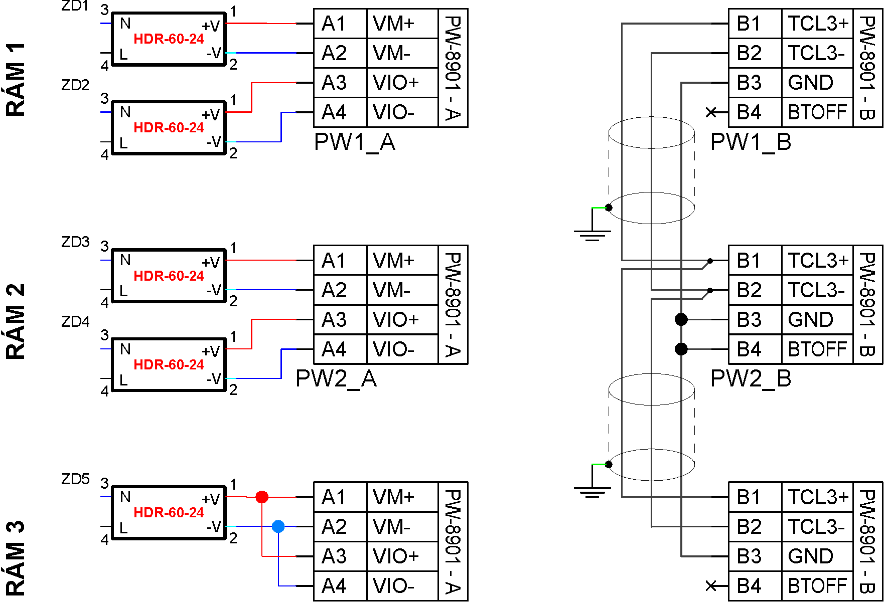
Fig. 1. TCL3 bus connection and power supply wiring for a TC800 assembly consisting of 3 frames.
Notes:
- The internal (pass-through) frames of the assembly must have the TCL3 bus impedance termination disabled. This is done by connecting terminal BTOFF (B4) to terminal GND (B3)
- The connection between frames (TCL3+ and TCL3- signals) must be made using a suitable shielded cable (a cable compliant with RS-485 at 5 Mbit/s; for example, an STP cable can be used).
- The cable must be strictly straight, without any branches—as shown in the example. The GND signal (terminal B3) can be connected less strictly (e.g., using a spare pair in the communication cable).
- At a speed of 5 Mbit/s, the maximum length of the TCL3 bus is approximately 20–30 m.
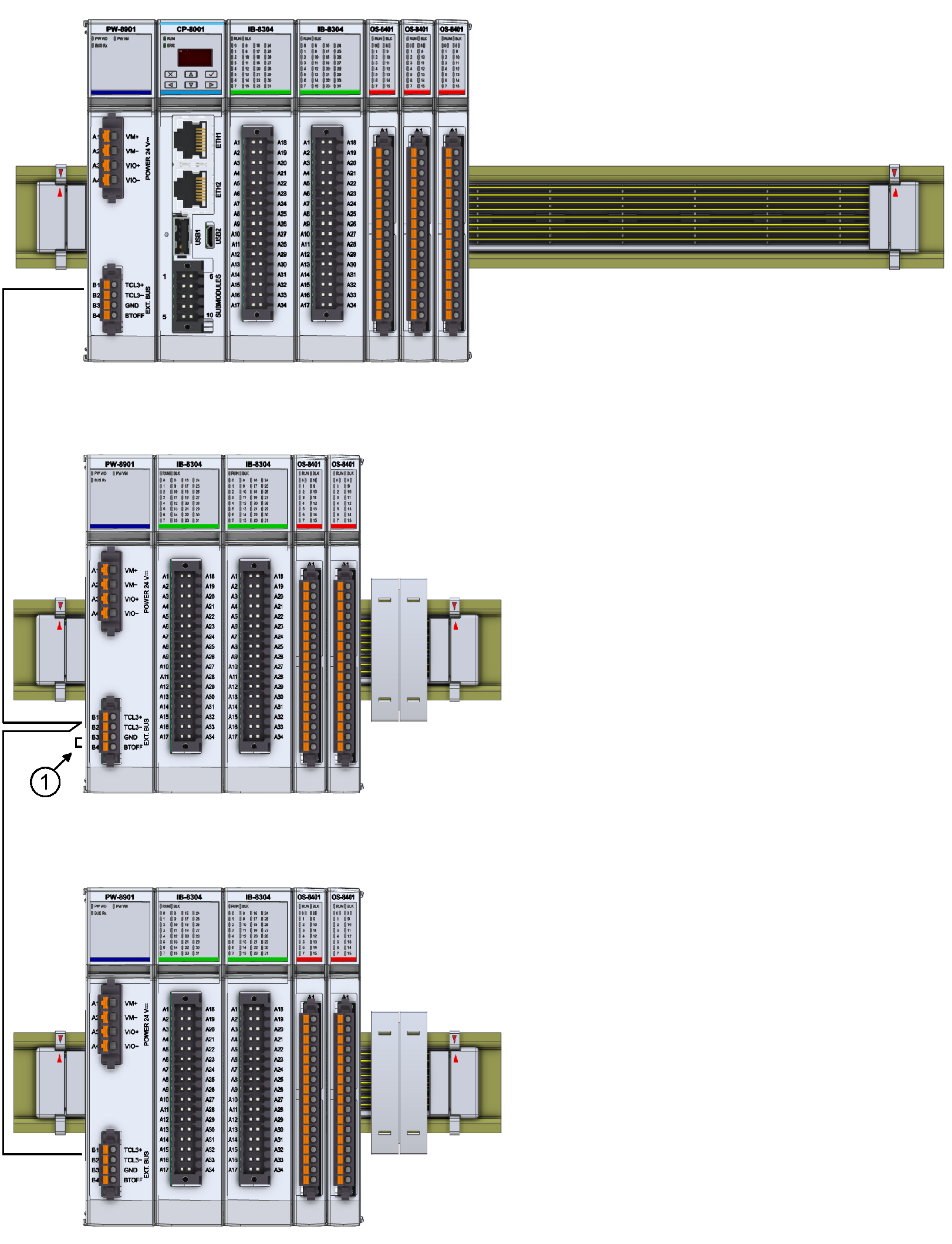
Fig. 2. Diagram of TCL3 bus connections for a 3-frame assembly, as shown in Fig. 1
Notes:
- The frame must have the TCL3 bus termination disabled; see point (1) in the figure
- The configuration shown here has a base module (CP-8001) in the first frame; the remaining two frames contain only peripheral modules and a power supply module (PW-8901)
- Each module must be assigned a unique address within the assembly (addresses must not be repeated, even among modules in different frames of the assembly)
- The GND terminal (B3) and the TCL3 connection (entire connector B) are galvanically isolated from all other circuits of the TC800 system assembly.