
The PW-8901 power supply module is designed to power TECOMAT TC800 PLC assemblies from a 24 V DC network in a 24 mm wide case.
It is a module that provides power for internal circuits (VM) and IO circuits (VIO) with an output level of 24 V SELV (circuits with low safe voltage protection). Part of the source is a block for monitoring mains voltage failure. The output level is equipped with protective overvoltage elements.
The module provides power for both the system's internal circuits (24 VDC source connected to terminals A1 and A2 (VM level)), as well as IO parts and peripheral circuits connected to the system's peripheral modules (24 VDC source connected to terminals A3 and A4 (VIO level).
Both power inputs are galvanically isolated from each other. When using two separate power supplies, this separation is ensured, providing higher protection against possible interference that reaches the IO circuits of the peripheral modules. An example of this separate power supply is for frame 1 and frame 2 in Fig.2.
For smaller assemblies, it is possible to connect both power inputs (VM and VIO) and power them from one common source. This cancels the galvanic isolation of the IO parts of some peripherals from the internal circuits. An example of a common power supply is for frame 3 in Fig.2.
The connectors for connecting the 24 V DC supply voltages are screwless.
Detailed connection data, principles of correct installation, connection examples and principles of increasing resistance and reliability are given in the Manual for designing programmable automata TECOMAT TXV 001 08.01.
 |
It is not permissible to remove or insert the power module into the system when it is switched on! If we are handling the power supply module, it must be switched off! The system can be turned on if it is powered by another power module. |
|
Type |
Description |
Ord. number |
|
PW-8901 |
power supply from the 24 V DC network |
TXN 189 01 |
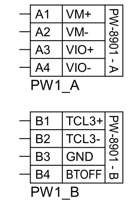
Fig. 1 Connectors on the front of the PW-8901 module
Note:
- Connector A is intended for connecting the main power supply of the system, both its internal circuits (VM) and peripheral circuits of the modules, respectively. and external IO circuits (VIO).
- The VM power supply assumes the connection of a 24 VDC low safe voltage (SELV) source, the maximum required power is given by the sum of the VM power consumption of all modules of the given frame.
- The VIO power supply assumes the connection of a safe small voltage (SELV) source of 24 VDC, the maximum required power is given by the sum of the VIO power consumption of all modules of the given frame.
- The VM and VIO levels are galvanically isolated from each other. In the case of small installations without the risk of major interference, which could reach the internal circuits of the system after powering up, it is possible to connect both inputs on connector A (VM with VIO) and power them from a common source
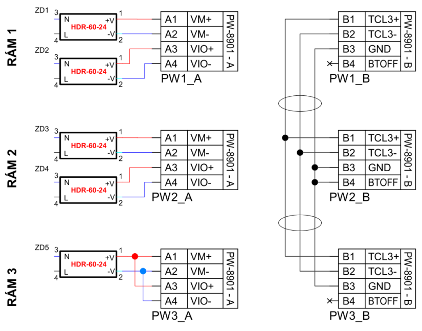
Fig. 2 Example of connecting the TCL3 bus on PW-8901 modules for a PLC assembly with three frames
Notes:
- The TCL3 bus corresponds in its characteristics to the RS-485 interface at a speed of 3 Mbd, i.e. suitable shielded cables for this interface and communication speed
- The bus is intended only for connecting TC800 frames, a TCL3 interface module (PW-8901) must be installed in each frame, the bus must always be a line (without branches).
- The maximum length of the entire TCL3 line is max. 100 m.
- For pass-through modules (frame 2 in the example), the bus termination must be switched off, which is switched on when terminal B4 (BTOFF) is not connected. I.e. it is necessary to connect terminal B4 (BTOFF) to signal ground B3 (GND).