Four levels of protection against lightning (LPL) have been introduced to meet the requirements of the ČSN EN 62305 standard. Each level includes a set of maximum and minimum values.
Requirements for the design of the SPD are based on these values. The re quirements for suppressing capability of lightning current supressor in buildings on the LPL I level of protection are in total Iimp =100 kA; on the LPL II level there is the requirement to supress safely 75 kA currents, and on the LPL III and IV level the total is 50 kA.
Examples of connections and the recommended elements described in the following chapters only consider the LPL III and LPL IV levels of protection.
For these levels, the value of the peak current is I= 100 kA.
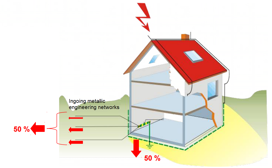
The separation of the lightning current during a discharge into a building
In a simplified way it can be said that 50 % of the lightning current is dissipated via the LPS into the ground, and the remaining 50 % may end up at random in various leakages and conductive inlets; it is split approximately evenly, provided the diameter of the leads is sufficient to conduct a partial lightning current. Data networks, due to the small cross section of wires, can only absorb a maximum of 5% of the total lightning current.
The considered lightning current amplitude depends on the selected level of LPL.
The current is again split into individual wires almost evenly. In the TN-CS networks, the partial lightning currents in individual conductors are considered as in the TN-C. In TN-S, the currents can be in some cases divided into 5 wires.
An example: If the 3ph TN-C (3+0) supply to the house is considered, and the utilities (water, gas) use plastic pipes, so they are not considered. A possible telephone cable can be ignored. The resulting value of the lightning current at the house inlet is 50 kA (50 % of the peak current).
A table for the selection of leakage capabilities Iimp for power lines:
An example: for LPL III and LPL IV, a 50 kA lightning current and the TN-C 3+0 network, the resulting SPD suppressing capability is 12.5 kA
|
|
Low voltage network |
|||||
|
LPL |
Maximum current in the particular LPL |
The number of wires (n) |
TN-C |
TN-S |
||
|
|
The connection mode |
|||||
|
|
CT1 |
CT2 |
||||
|
L-PEN |
L-PE N-PE |
L-N |
L-PE |
|||
|
1 or unknown |
200 kA |
|
Iimp (kA) |
|||
|
5 |
- |
20 |
20 |
80 |
||
|
4 |
25 |
- |
- |
- |
||
|
3 |
- |
33.3 |
33.3 |
66.7 |
||
|
2 |
50 |
- |
- |
- |
||
|
2 |
150 kA |
|
Iimp (kA) |
|||
|
5 |
- |
15 |
15 |
60 |
||
|
4 |
18,8 |
- |
- |
- |
||
|
3 |
- |
25 |
25 |
50 |
||
|
2 |
37.5 |
- |
- |
- |
||
|
3 or 4 |
100 kA |
|
Iimp (kA) |
|||
|
5 |
- |
10 |
10 |
40 |
||
|
4 |
12,5 |
- |
- |
- |
||
|
3 |
- |
16,7 |
16,7 |
33.3 |
||
|
2 |
25 |
- |
- |
- |
||
An example: for LPL III and LPL IV, a 50 kA lightning current and the TN-C 3+0 network, the resulting SPD suppressing capability is 12.5 kA
In accordance with IEC 61643-11, the surge suppressors (SPD) are designated:
Type 1 (sometimes referred to as B), Type 2 (C), Type 3 (D)
Decisive parameters defining the SPD
1) The supply network
Network – TN - TN-C
- TN-CS
- TN-S
Network - TT - SPD (1+1; 3+1) TN-S (cannot be used (2+0; 4+0) TN-S)
Network - IT - special SPD for the IT network
2) A maximum continuous operating voltage Uc
The highest voltage that can be continuously connected to SPD terminals must be equal to or higher than the nominal voltageof the network. Keep in mind the DC for PV systems!
3) Impulse current Iimp (10/350 µs)
For the classification of the SPD type 1
- The SPD must safely divert this current underground - without any apparent damage
- without departing from the thermal stability
- it must not show signs of a breakdown or a flashover
4) A MAXIMUM DISCHARGE CURRENT Imax (8/20 µs)
- the peak value of current flowing through the SPD (8/20)
For the SPD classification type 1 and type 2
The SPD must safely direct this current underground - : - with no apparent damage
- without departing from the thermal stability
- it must not show signs of a breakdown or a flashover
- it must not show any signs of a breakdown
5) Rated discharge current In (8/20 µs)
The peak value of the current flowing through the SPD with the shape of a current pulse 8/20 is used for the classification of SPD tests for type 1 and type 2. The SPD must be able to discharge this current at least 15 times without any substantial changes of properties.
6) Voltage protection level Up
A maximum level of the voltage measured at the SPD terminals during the application of the test pulses with a set waveform and amplitude.
Up – must be lower than the pulse withstand voltage UW of the protected device !
7) Impulse withstand voltage UW
The UWimpulse withstand voltagefor power lines and terminals should be specified in accordance with the IEC 60664-1. The telecommunication lines and terminal facilities are guided by the ITU-T K20 and K21, other lines and terminals according to information obtained from the manufacturer.

Surge protection
Overvoltage
The voltage exceeding the maximum permissible value of the operating voltage in an electrical circuit.
Types of overvoltage
switching overvoltage
atmospheric overvoltage
Pulse withstand voltage Uimp
ČSN EN 60664-1
for low voltage networks 230/400 V
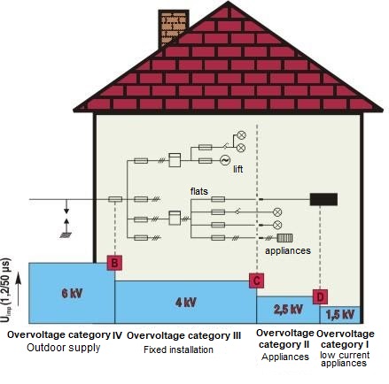
The pulse withstand category IV 6 kV equipment is intended for use at the beginning of electrical installations in buildings. Examples of such equipment include electricity meters, circuit breakers, fuses, RCDs, etc.
The pulse withstand category III 4 kV equipment is a part of the fixed electrical installations; it also includes facilities with special requirements for reliability and usability. Examples of such devices may include, among others, electrical appliances (e.g. circuit breakers, fuses, disconnectors, contactors, RCDs, etc.).
The pulse withstand category II 2.5 kV equipment is intended for connection to the fixed electrical installations.
Examples of such equipment include portable electrical tools, household appliances, etc.
The pulse withstand category I 1.5 kV equipment (the category of overvoltage I) is intended for connection to the circuits, in which measures have been taken to reduce transients overvoltages to the required low level.
The division of the building into so-called Lightning protection zones (LPZ) and the placement of SPD.
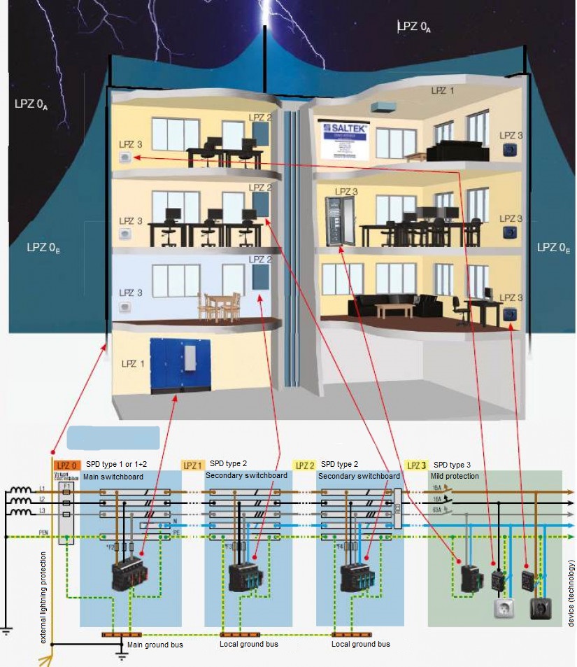
The principle of reducing the surge using zones involves a gradual reduction in the level of surge to a safe level that does not harm the equipment or technology. In order to achieve safe levels of surge, the entire building is divided into individual zones and on the boundaries between zones, SPD is installed.
LPZ 0A :
The zones whose points are exposed to being directly struck by a lightning, and therefore they could carry the full lightning current. An unattenuated electromagnetic field occurs here..
LPZ 0B :
The zones whose points are not exposed to direct strikes of a lightning, there are unattenuated electromagnetic fields.
LPZ 1 :
The zones whose points have not been directly struck by a lightning, and where the currents in all conductive parts have been significantly reduced compared with zones LPZ 0A and LPZ 0B. In these zones the electromagnetic field may be attenuated.
The subsequent zones (LPZ 2, etc.):
If further reduction of leakage currents or electromagnetic fields is required, it is necessary to design the so-called subsequent zones.
A standard recommendation is to insert the so-called 1st degree of protection at the LPZ 0 → 1 interface, specifically the I. class lightning surge suppressor tested by the lightning current Iimp(10/350). The LPZ 1 → 2 interface should be fitted with the 2nd degree of protection - a class II surge voltage arrester tested by the test impulse In (8/20). It is further recommended to fit in the LPZ 2 → 3 interface and also along the continuing line every approx. 10 meters the so-called 3rd stage of protection, class III, also tested by the test impulse Imax(8/20).
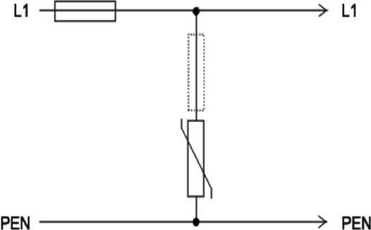
Connecting in the mode"3+1"

Backup fuse
If the main fuse F1 has a higher value than the recommended backup fuse of the manufacturer, the recommended F2 backup fuse should be put upstream from the SPD (fuses with the characteristics gL/gG).