
A number of designs can use the wall-mounted version of the module with a small graphic display. The module is always executed with respect to the particular electrical installation design, comprising a display (with the display of two measured values and several symbols), push-buttons (for temperature correction and a change of mode), and an internal temperature and relative humidity (RH) sensor, as well as outputs for the connection of an external temperature sensor, such as the floor temperature.
The module consists of two parts. The internal part contains the sensor electronics and is terminated with a 4-pole terminal block with terminated CIB, an external temperature sensor and a connector, where the cable from the other part is inserted.
The second part represents a wall-mounted design feature (e.g. Logus - see the figure at the end of this chapter) with its own display, push-buttons and a temperature and RH sensors terminated on a 70 mm cable with a connector. The second temperature sensor (Pt1000, Ni1000, N TC 12 k or NTC up to 1)60k is e.g. for measuring the floor temperature.
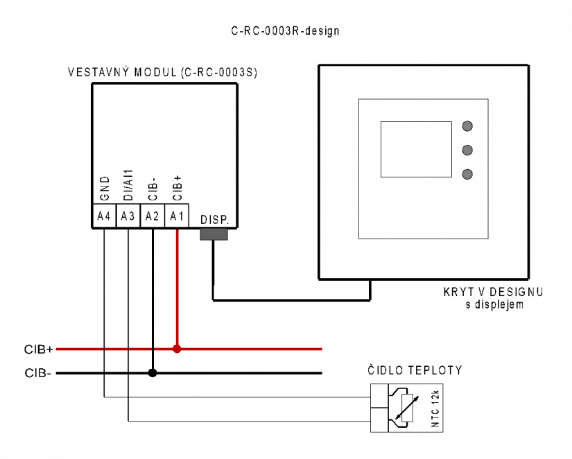
Fig. 1. An example of connecting the C-RC-0003R-design control module, including the external temperature sensor
Notes:
-
The external temperature sensor must be the Pt1000, Ni1000, KTY81-121, NTC 12k or some other NTC with the resistance of up to 160k, the connection cable can be up to dozens of meters long. A typical use is for a floor sensor, the recommended cables include e.g. the SYKFY or similar cables, with at least 1x2 wires with 0.5 mm diameter.
-
The module should be installed in a standard flush box (KU68).
-
Some design variants (e.g. UNICA) have displays without a backlight – a specific design and its characteristics have to be consulted with the Teco a. s. commercial department.
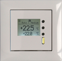
Fig. 2. An example of display in the Efapel Logus design