
Contact-free reading of cards and similar identifiers in accordance with the standards such as Unique 125 kHz and Mifare, DESFire Mifare 13.56 MHz can be facilitated by the AXR-100/110 sensors (manufactured by EFG CZ s.r.o), which should be connected to the C-WG-0503S module.
The module provides powering the sensor, communication between the Wiegand and the sensor, and control LEDs and the buzzer.
The sensor is suitable for the door; it can be installed on the door frame. Detailed technical information on the sensor can be found at the end of this chapter.
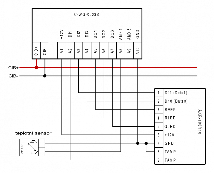
Fig. 1. An example of connecting the AXR-100/110 sensor to the C-WG-0503S module
Notes:
-
The cable for connecting the sensor can be as long as dozens of meters (the Wiegand interface allows the length of up to 150m); preferably the cable should be shielded with the minimum cross section of 0.35 mm2.
-
The consumption of the AXR-100 sensor from the supply voltage is specified at 112 mA, but this is impulse consumption; the average current level approximately 50 mA and it meets the specifications of the C-WG-0503S module (maximum consumptiuon from the 12 V output is 60 mA).
-
The free inputs AI/DI4 and AI/DI5 can be utilized e.g. for connecting the temperature sensors (measuring the temperature in the room, etc.).
The properties and parameters of the AXR-100 and AXR-110 sensors.
The AXR-100/110 sensor is designed for contact-free reading (RFID) identifiers in accordance with the type of technology used: the Unique/HS (AXR-100) or the Mifare (AXR-110). The coloured LED on the front side of the sensor informs about the reading of the identifier, together with an audible signal (a buzzer controlled by connecting the terminal 3 (BEEP) with the clamp (7) GND). The LED indicates 3 statuses:
1) Blue - idle operation state.
2) Green - access allowed (controlled by connecting terminal 5 (GLED) with terminal (7) GND).
3) Red - No Entry (controlled by connecting terminal 4 (RLED) with terminal (7) GND).
Tab. 1. Basic parameters of the AXR-100/AXR-110 sensor
|
Technical parameters |
AXR-100 |
AXR-110 |
|
Nominal supply voltage |
12 VDC |
|
|
Maximum current consumption |
112 mA 1) |
75 mA 1) |
|
The Wiegand interface |
26/42 bits (3/5 Byte) |
Wiegand 42 bits (5 Byte) |
|
Reading distance – ISO card |
max. 10.5 cm 2) 3) |
max. 7 cm 2) 3) |
|
Reading distance - the Tearshape pendant |
max. 5 cm 2) 3) |
max. 3.5 cm 2) 3) |
|
Reading distance - the Keyfob pendant |
max. 7 cm 2) 3) |
max. 3.5 cm 2) 3) |
|
The RFID frequency range |
125 kHz |
13.56 Mhz |
|
The type of sensor |
just for reading (read only) |
|
|
The supported types of identifiers |
EM4100 |
ISO 14443A Mifare4) ISO 14443A DESFire4) |
|
Acoustic signal |
buzzer |
|
|
Optical indication |
LED (blue, green, red) |
|
|
Terminal block |
A screw connector |
|
|
Screw |
M2, thew material is CB4FF+Zn |
|
|
Terminal |
Cu Zn40 Pb2+Ni |
|
|
Contact |
CuSn7+Ni |
|
|
Tightening torque for the terminal screws |
0.4 Nm |
|
|
Maximum cross-section of the connected wire |
6 mm2 |
|
|
The sensor dimensions (width x height x depth) |
42 x 120 x 40 mm |
|
|
The dimensions of the housing (width x height x depth) |
45 x 124 x 41 mm |
|
|
The range of operating temperatures |
-20 to +50 °C |
|
|
Protection |
IP 54 5) |
|
-
The median value of the pulse current is less than 60mA, so it can be directly supplied by a 12 V output in the C-WG-0503S module.
-
This measurement is for the identifiers supplied with the sensor. Other types of ID may have a different reading distance.
-
It has been measured on a non-metallic surface. Metallic surface can decrease the reading distance.
-
Only for reading of a unique serial card number.
-
The declared protection is valid only if the proper installation procedure has been followed.
Colour variations of the housing (optional accessories):
H-100/B housing of the AXR-100 sensor, black
H-100/W housing of the AXR-100 sensor, white
H-100/G housing of the AXR-100 sensor, grey
H-100/T housing of the AXR-100 sensor, titanium
H-100/R housing of the AXR-100 sensor, red
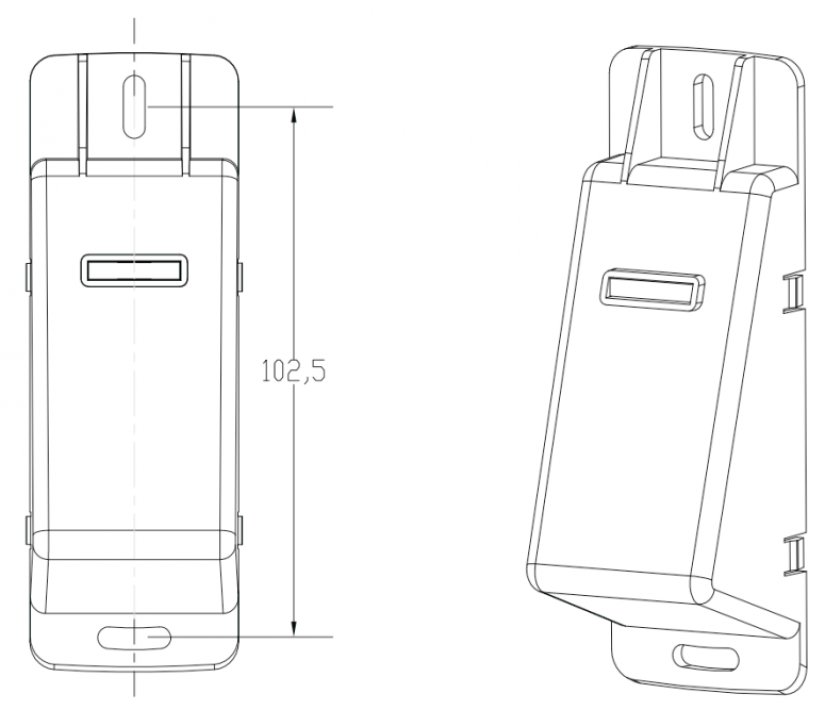
Fig. 2. The mounting dimensions of the AXR-100/110 sensor (a view without the top cover)
Notes:
-
The recommended mounting height is 120 cm from the floor to the bottom edge of the sensor.
-
There is room in the rear part of the sensor for the connector and the cable.
-
The coloured top cover (see the variants in the text above) can be fixed by its snapping onto the sensor.
Table.2: A description of terminals and signals of the AXR-100/AXR-110 sensor connector.
|
Connector PIN |
Function |
Description |
|
1 |
D11(D21) |
The data wire Data 1 Wiegand interface |
|
2 |
D10(D20) |
The data wire Data 0 Wiegand interface |
|
3 |
BEEP |
Buzzer (inside pull-up on +5 V, switching at zero) |
|
4 |
RLED |
Red LED (inside pull-up on +5 V, switching at zero) |
|
5 |
GLED |
Green LED (inside pull-up on +5 V, switching at zero) |
|
6 |
+12V |
positive pole of the supply voltage |
|
7 |
GND |
the ground of the supply voltage |
|
8 |
TAMPER |
Protective loop, inside the sensor connected to pin No. 9 |
|
9 |
TAMPER |
Protective loop, inside the sensor connected to pin No. 8 |
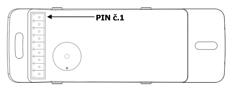
Fig. 3. Placement of the connector on the rear side of the AXR-100/110 module (a rear view)